
Solar electric generator

a solar energy and generator technology, applied in the field of alternative energy, can solve the problems of dramatic reduction in efficiency, and much scientific debate, and achieve the effect of reducing friction

Inactive Publication Date: 2012-08-16
SOLSPIN ELECTRIC
View PDF6 Cites 14 Cited by
  • Summary
  • Abstract
  • Description
  • Claims
  • Application Information

AI Technical Summary

Benefits of technology

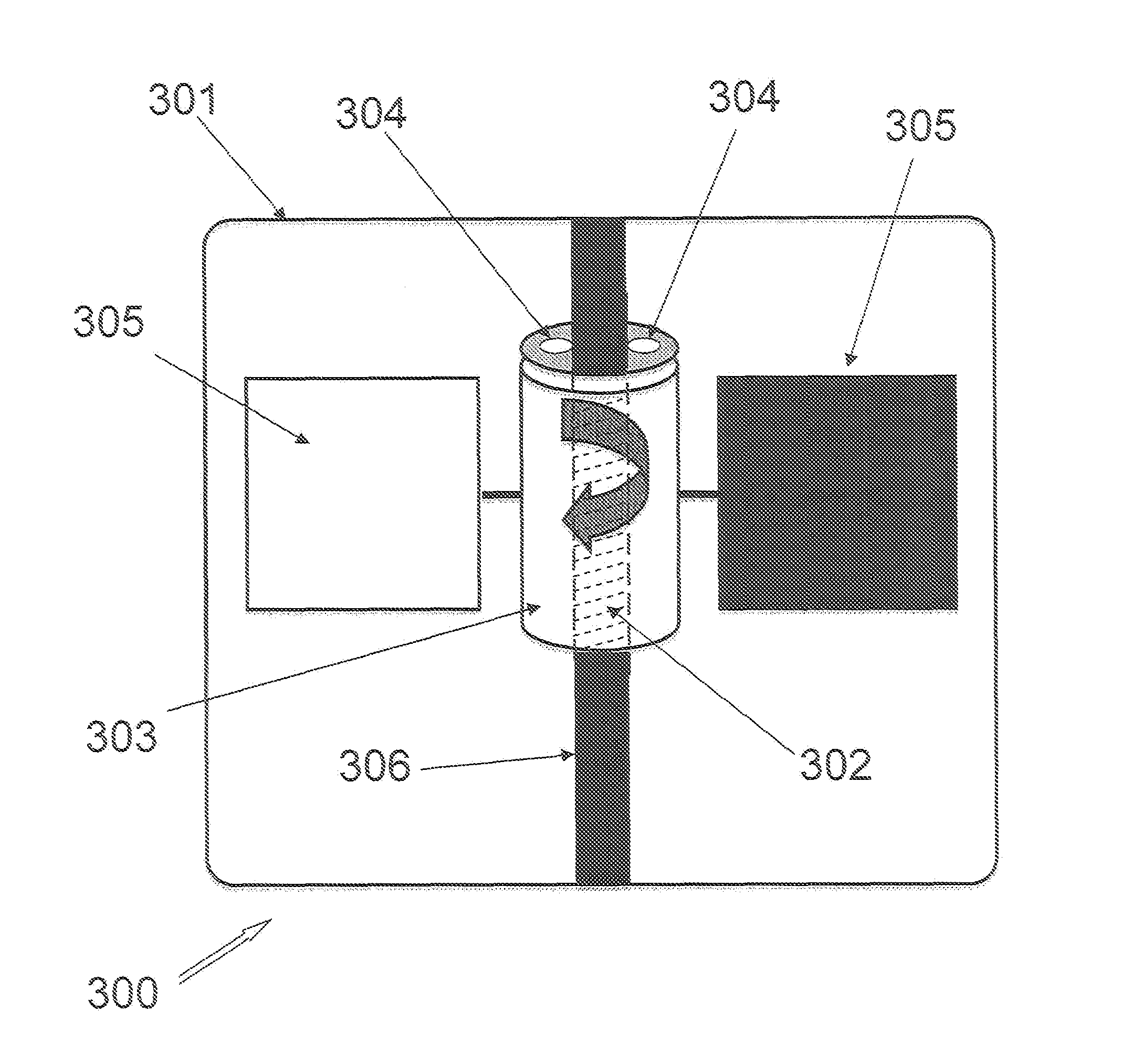
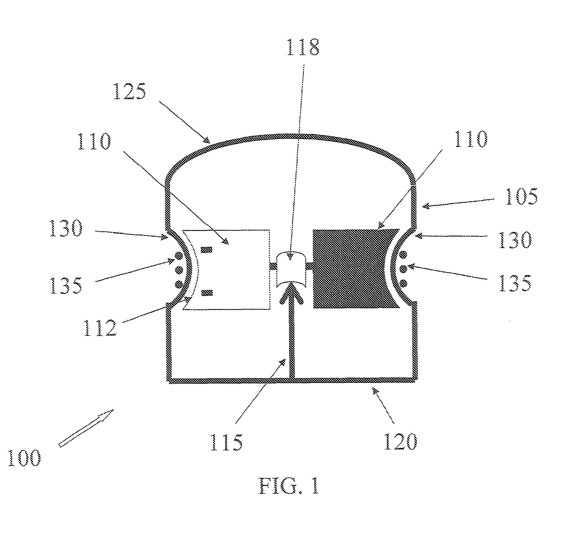
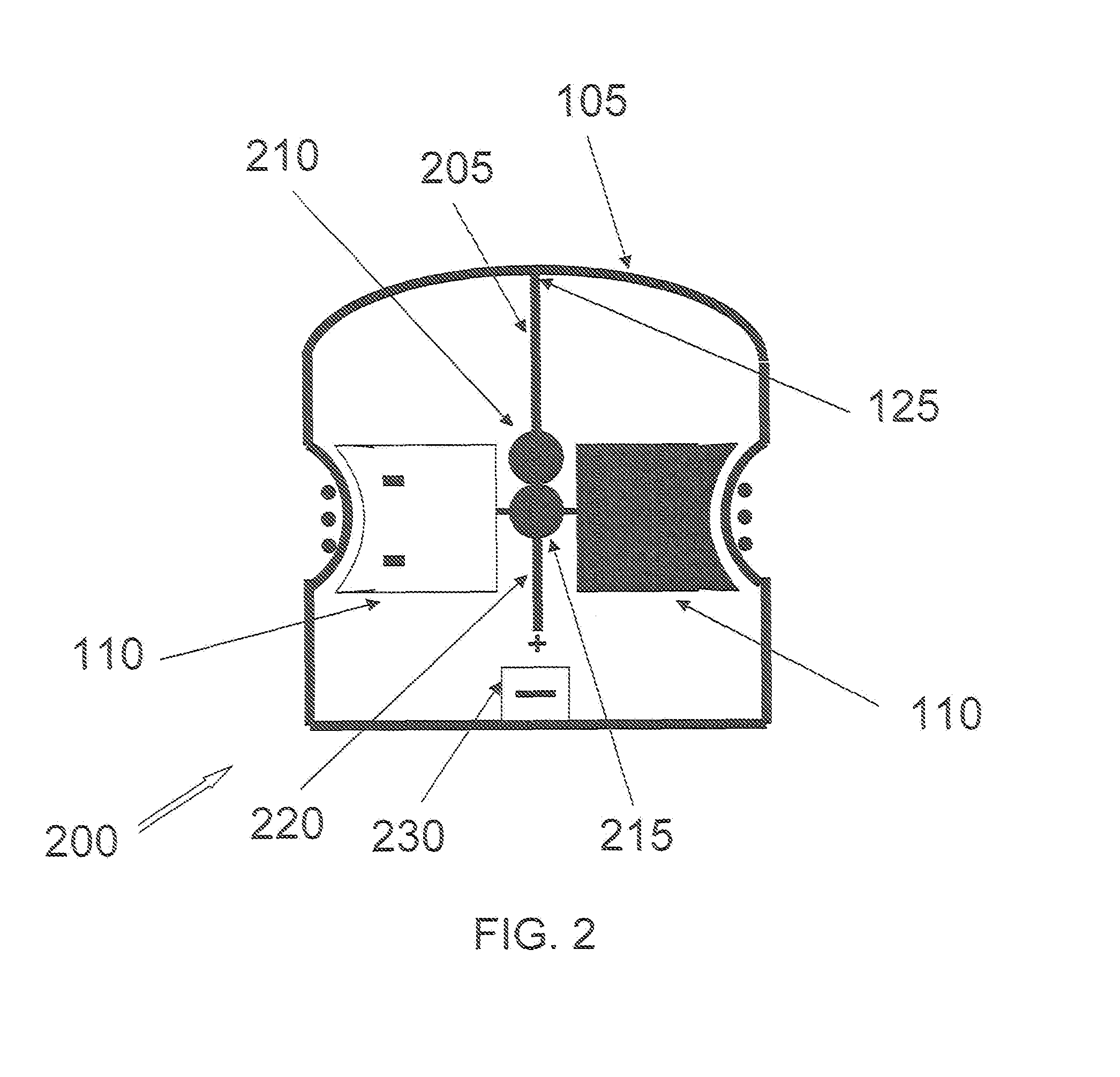
[0012]In another embodiment, the method includes positioning a plurality of alternately positioned vanes on a tubular magnet with alternating poles, the hollow portion of which is mounted on ceramic bearings designed to minimize friction which in turn is attached to the center axis within a sealed cylindrical casing, the vanes having a white side and a black side, coiling a magnetic wire along a center axis of the casing, and exposing the vanes to light to create a pressure differential between the black and white sides of the vanes and rotate the plurality of alternately positioned vanes, thereby creating AC.

Problems solved by technology

The reason for the rotation has been the cause of much scientific debate.
At these very high vacuums the effect of photon radiation pressure on the vanes can be observed in a very sensitive apparatus, but the radiation pressure is insufficient to cause rotation.
However, the apparatus described in U.S. Pat. No. 359,748 does not depend on the rotation of magnets and leads to a dramatic decrease in efficiency.
In U.S. Pat. Nos. 406,968 and 4,397,150, incorporation of rotating gears leads to a dramatic decrease in efficiency due to friction from the rotation of the gears.
However, all of the previously described methods have not been successfully pursued due to the inefficiency of producing the electric current.

Method used


Image

  • Solar electric generator
  • Solar electric generator
  • Solar electric generator

Examples


example 1

[0055]Various prototypes of the SEG have been made and a detectable AC current was produced. Accordingly, the next step is optimizing the power to weight ratio of the magnetized vanes.

[0056]In this experiment, the casing was approximately 10 cm high having a dome-like top and a diameter of about 7 cm. Ambient temperature was approximately 84° F., with weak sunlight. Copper wire was coiled around the casing proximate to the rotating vanes at approximately 2.75 cm from the base. The amount of AC generated was 80 microamps using 4 NdFeB magnets (N38) with a BrMax of 12,500 gauss. The irradiance was not measured. Rotations per minute (RPM) were not measured, nor was the proximity to the coiled copper wires. A larger number of stronger and lighter magnets will be used while maximizing the RPM and the number, gauge and material of coiled wires. Also, minimizing the proximity of the wires will help considerably as will minimizing the radius of the vane design.


PUM

PropertyMeasurementUnit
thickaaaaaaaaaa
viscosityaaaaaaaaaa
pressuresaaaaaaaaaa

Abstract

A solar electric generator is disclosed that includes a sealed cylindrical casing having a depression in the cylindrical wall, the casing being made of a material that allows the energy of sunlight therethrough, a magnetic wire coiled in the depression, a strut positioned within the casing along a center axis, and a plurality of magnetized vanes configured to rotate (with low friction) on the strut proximate the depression, the vanes having a black side and a white side, an outer portion of the vane being shaped to correspond to the depression in the casing. Other embodiments and methods of generating an alternating current are also disclosed.

Description

BACKGROUND OF THE INVENTION[0001]1. Field of the Invention[0002]The invention relates generally to alternative energy, and more specifically to use solar energy to generate an electric current.[0003]2. Background Information[0004]The Crookes radiometer, also known as the light mill or solar engine, consists of an airtight glass bulb, containing a partial vacuum. Inside are a set of vanes that are mounted on a spindle, which rotates when exposed to light. The reason for the rotation has been the cause of much scientific debate.[0005]The radiometer was invented in 1873 by the chemist, Sir William Crookes, as the by-product of chemical research. In the course of very accurate quantitative chemical work, Crooke was weighing samples in a partially evacuated chamber to reduce the effect of air currents, and noticed the weighings were disturbed when sunlight shone on the balance. Investigating this effect, Crooke created the device, which is still manufactured and sold to this day as a cur...

Claims


Application Information

Patent Timeline
Patent Type & Authority Applications(United States)
IPC IPC(8): H02N10/00H02K15/00F03G6/00
CPCF03G7/00Y10T29/49009Y02E10/46F03G7/005F03G6/00F03G7/016
Inventor BATTAGLIA, ALEX
Owner SOLSPIN ELECTRIC
Learn More