Methods and apparatuses for inductive energy capture for fuzes

a technology of inductive energy and fuzes, which is applied in the direction of electric fuzes, combustion processes, lighting and heating apparatuses, etc., can solve the problems of no redirection of available energy to storage capacitors, storage capacitors starting to charge, etc., and achieve the effect of improving power delivery efficiency

Active Publication Date: 2012-08-16
NORTHROP GRUMMAN SYST CORP
View PDF8 Cites 4 Cited by
  • Summary
  • Abstract
  • Description
  • Claims
  • Application Information

AI Technical Summary

Benefits of technology

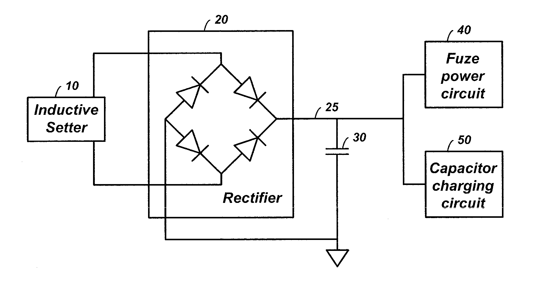
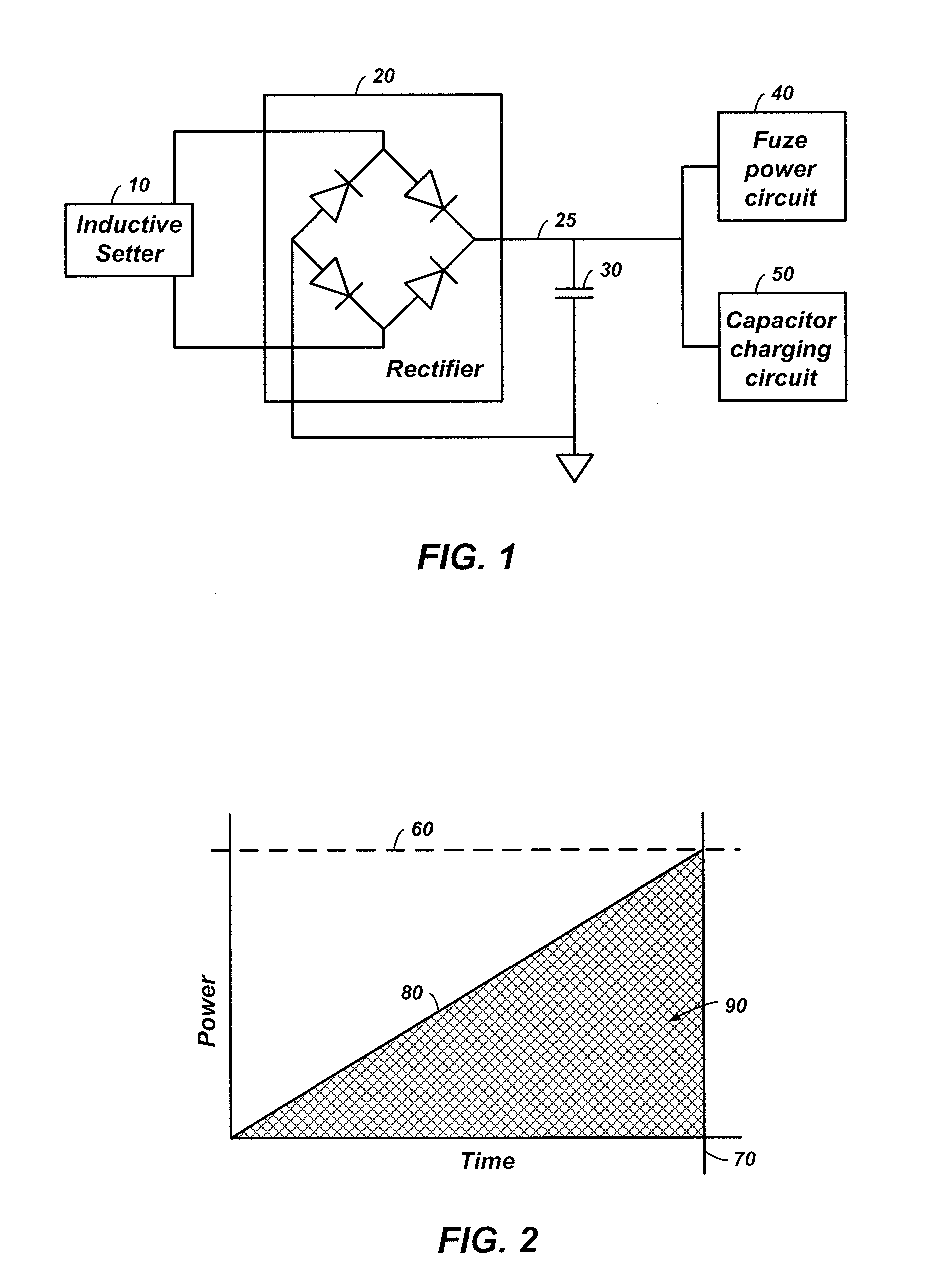
[0009]There is a need to improve the efficiency of power delivery to charge storage devices and fuze electronics with power supplies and power needs that vary over time.

Problems solved by technology

However, the energy storage capacitor starts to charge from zero volts, which appears as a virtual short circuit to a DC power source.
In addition, as the fuze load changes during the setting operation, (e.g., components are powered down after their data transfer is complete) there is no redirection of available energy to the storage capacitor.

Method used


Image

  • Methods and apparatuses for inductive energy capture for fuzes
  • Methods and apparatuses for inductive energy capture for fuzes
  • Methods and apparatuses for inductive energy capture for fuzes

Examples


Embodiment Construction

[0021]In the following detailed description, reference is made to the accompanying drawings which form a part hereof, and in which is shown by way of illustration specific embodiments in which the invention may be practiced. These embodiments are described in sufficient detail to enable those of ordinary skill in the art to practice the invention. It should be understood, however, that the detailed description and the specific examples, while indicating examples of embodiments of the invention, are given by way of illustration only and not by way of limitation. From this disclosure, various substitutions, modifications, additions rearrangements, or combinations thereof within the scope of the present invention may be made and will become apparent to those skilled in the art.

[0022]In accordance with common practice the various features illustrated in the drawings may not be drawn to scale. The illustrations presented herein are not meant to be actual views of any particular method, d...


PUM


Abstract

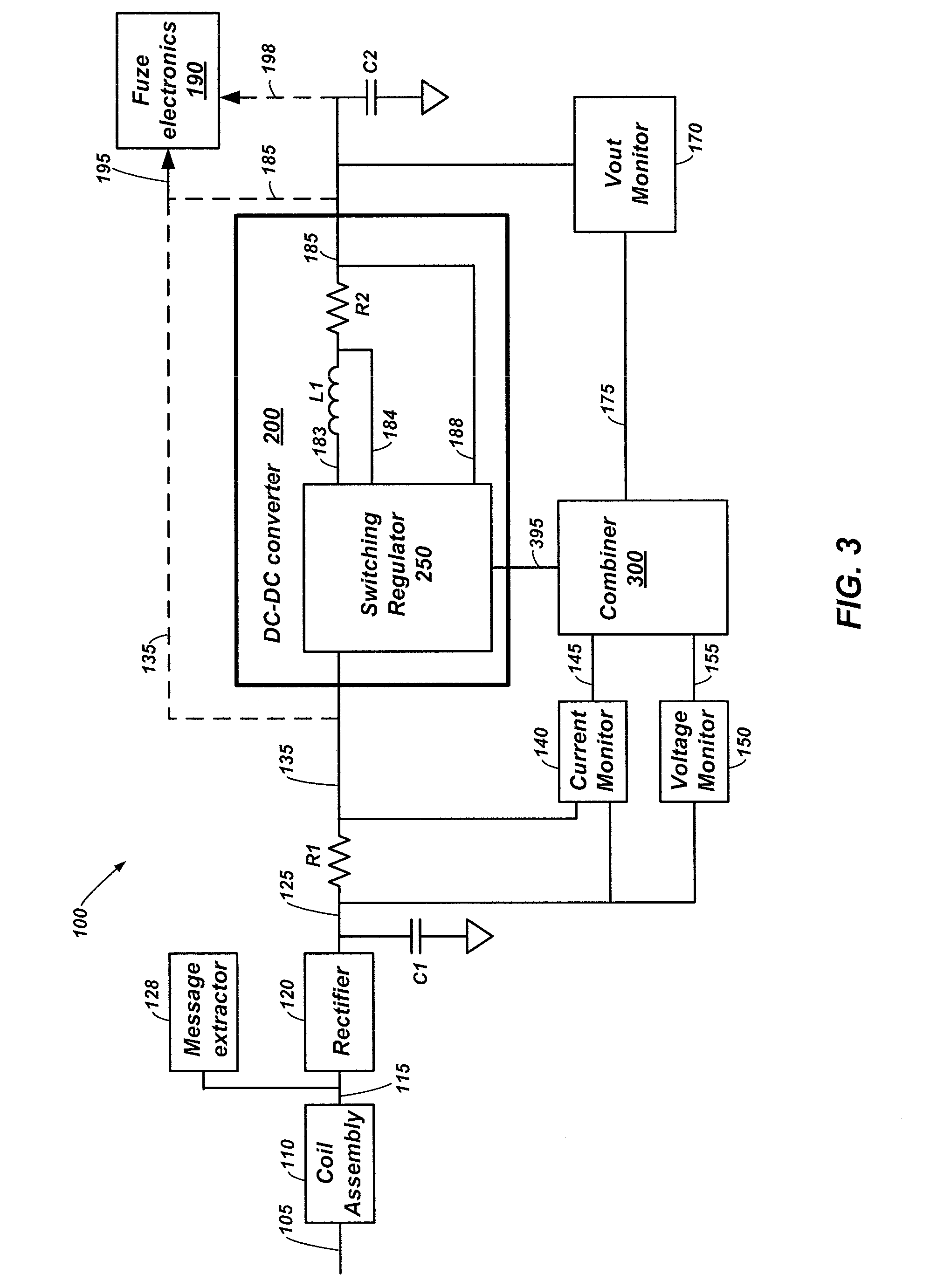
Methods and apparatuses are disclosed for power conversion in fuzes for projectiles. Fuze electronics in the projectile control detonation of the projectile. A rectifier converts pulses from a setter signal to a DC power source signal. A voltage monitor coupled to the power source signal generates a source voltage indicator and a current monitor coupled to the power source signal generates a source current indicator. A combiner generates a supplied power level indicator in response to a combination of the source voltage indicator and the source current indicator. A DC-DC converter uses the supplied power level indicator when converting the power source signal to a power output signal to adjust a current level of the power output for efficient charging of a charge storage device and delivery of power to the fuze electronics.

Description

STATEMENT REGARDING FEDERALLY SPONSORED RESEARCH OR DEVELOPMENT[0001]The U.S. Government has a paid-up license in this invention and the right in limited circumstances to require the patent owner to license others on reasonable terms as provided for by the terms of Contract No. DAAE30-01-9-0800 awarded by the Department of Defense.TECHNICAL FIELD[0002]Embodiments of the present invention relate generally to providing energy to fuzes for explosive projectiles and, more particularly, to controlling delivery of inductive power to charge storage devices and fuze electronics.BACKGROUND[0003]The following background description is provided to assist the understanding of the reader. None of the information provided or references cited in this background section is admitted to be prior art to the present invention.[0004]Fuzes for explosive projectiles often receive programming information from a message coil in a projectile launcher that uses Alternating Current (AC) signals through inducti...

Claims


Application Information

Patent Timeline
Patent Type & Authority Applications(United States)
IPC IPC(8): F42C19/12
CPCF42C19/12F42C11/04
Inventor RING, JAMES A.
Owner NORTHROP GRUMMAN SYST CORP
Why Eureka
Try Eureka