Plc-type demodulator and optical transmission system

a demodulator and optical transmission technology, applied in multiplex communication, instruments, optical elements, etc., can solve the problems of increasing the number of processes and the manufacturing cost, and achieve the effects of reducing the manufacturing cost, reducing the skew, and reducing the connection loss

Active Publication Date: 2012-08-16
FURUKAWA ELECTRIC CO LTD
View PDF2 Cites 47 Cited by
  • Summary
  • Abstract
  • Description
  • Claims
  • Application Information

AI Technical Summary

Benefits of technology

[0053]According to an aspect of the present invention, it is possible to realize a PLC-type demodulator that eliminates the connection loss between the polarization beam splitter and the 90-degree hybrid circuit and aims at reducing the manufacturing cost, and an optical transmission system using the same.
[0054]Further, according to another aspect of the present invention, it is possible to realize a high-performance PLC-type demodulator that reduces the skew between X- and Y-polarization components, and an optical transmission system using the same.

Problems solved by technology

Because of that, connection loss occurs and at the same time, alignment work and bonding work for the optical connection thereof are necessary, resulting in an increase in the number of processes and in the manufacturing cost.

Method used


Image

  • Plc-type demodulator and optical transmission system
  • Plc-type demodulator and optical transmission system
  • Plc-type demodulator and optical transmission system

Examples


first embodiment

[0082](PLC-Type DP-QPSK Demodulator )

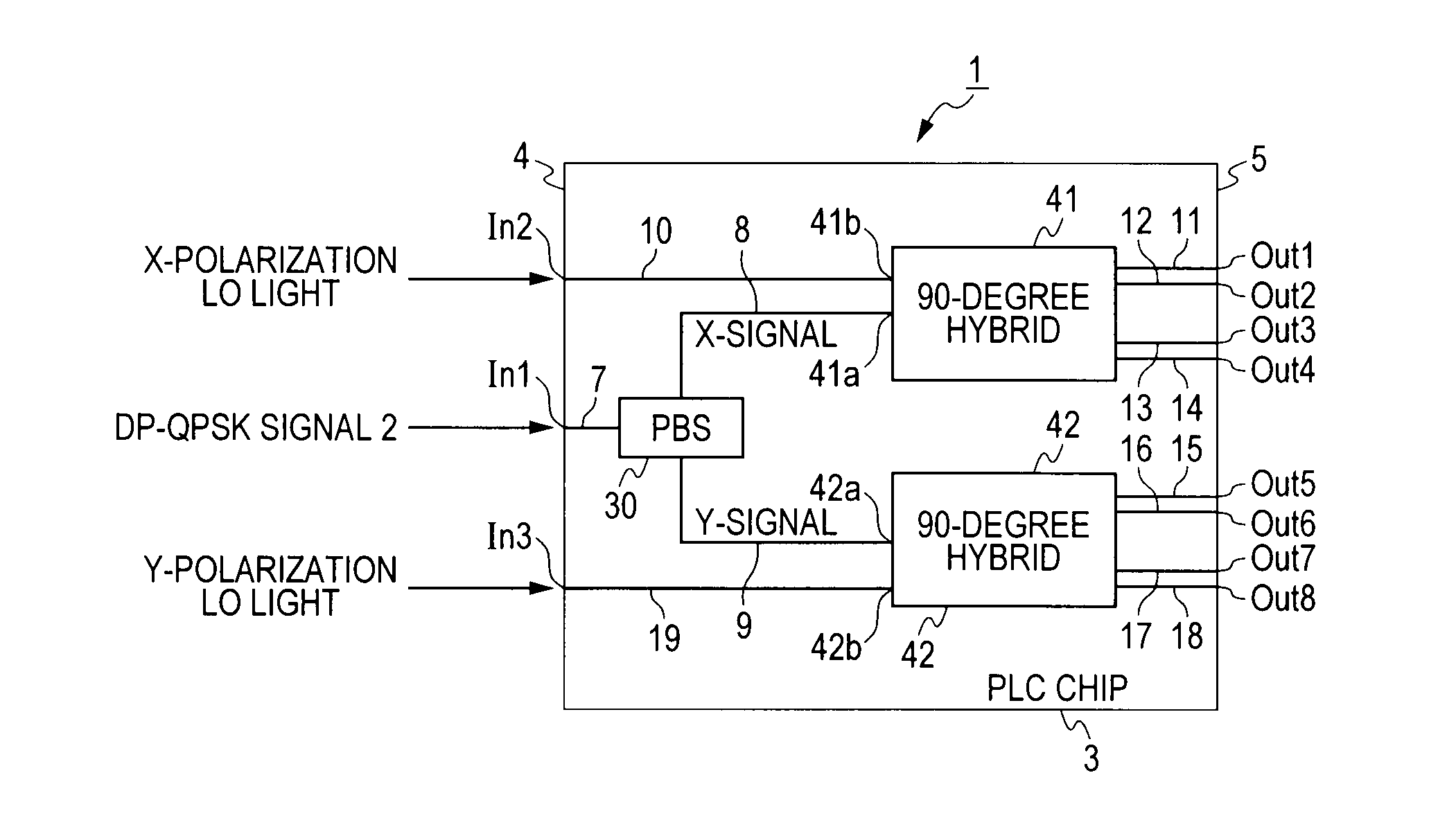
[0083]a PLC-type DP-QPSK demodulator 1 according to a first embodiment is explained based on FIG. 1 to FIG. 5.

[0084]The PLC-type DP-QPSK demodulator 1 is a DP-QPSK modulation system demodulator that receives, from a transmitter (not shown schematically), a DP-QPSK signal 2 formed by multiplexing an X-polarization QPSK signal and a Y-polarizing QPSK signal, which are obtained by performing quadrature phase shift keying on X-polarization light and Y-polarization light orthogonal to each other, respectively.

[0085]In the present specification, the “DP-QPSK demodulator” used in the DP-QPSK modulation system optical transmission system means a device to which a DP-QPSK signal (polarization-multiplexed quadrature phase shift keyed signal) formed by multiplexing an X-polarization QPSK signal and a Y-polarization QPSK signal is input, and which splits the signal into two orthogonal polarization components by a polarization beam splitter (PBS) and then mix...

second embodiment

[0117](PLC-Type DP-QPSK Demodulator )

[0118]FIG. 6 shows a basic configuration of a PLC-type DP-QPSK demodulator 1A according to a second embodiment.

[0119]In the PLC-type DP-QPSK modulator 1A, the number of the input ports of LO light is set to one in the PLC-type DP-QPSK demodulator 1 according to the first embodiment. In the present embodiment, as an example, only the input port In2 to which the X-polarization LO light is input is provided as an input port of LO light.

[0120]The demodulator 1A is configured so that the X-polarization LO light is branched into two within the PLC and each of the branched X-polarization LO light enters the 90-degree hybrid circuits 41, 42, respectively. The X-polarization LO light passes through the optical waveguide 10 and after branched into two to optical waveguides 10a, 10b, is incident on the 90-degree hybrid circuits 41, 42, respectively.

[0121]In the demodulator 1A, a half-wavelength plate (λ / 2 plate) 40 is inserted into the path through which on...

third embodiment

[0127](PLC-Type DP-QPSK Demodulator )

[0128]FIG. 7 shows a basic configuration of a PLC-type DP-QPSK demodulator 1B according to a third embodiment.

[0129]In the PLC-type DP-QPSK demodulator 1B, three PBSs, that is, the PBS 30 and PBSs 36, 37, are provided within PLC of the PLC chip 3 in the PLC-type DP-QPSK demodulator 1 according to the first embodiment. The second PBS(X) 36 and the second PBS(Y) 37 are cascade-connected to the first PBS 30, respectively. Further, in the demodulator 1B, in order to make an attempt to downsize the PLC chip 3, the PBSs 36 and 37 and the two 90-degree hybrid circuits 41, 42 are put in the proximity of each other in the spatial arrangement.

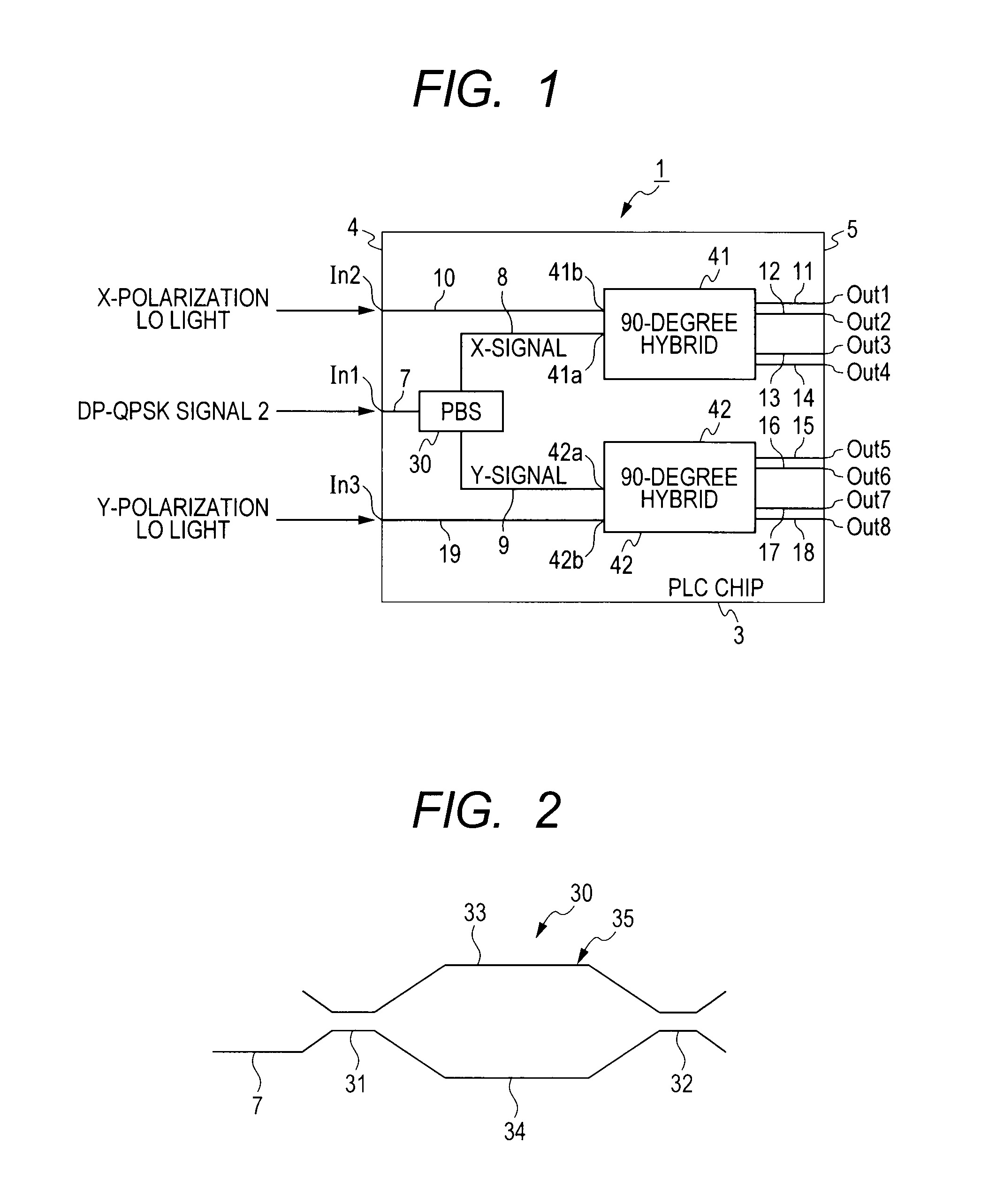
[0130]The PBSs 36, 37 are each a MZI that has two couplers and the two arm waveguides 33, 34 connected between both the couplers as the PBS 30 in the demodulator 1 according to the first embodiment (see FIG. 2).

[0131]In the demodulator 1B, first, the DP-QPSK signal 2 input from the input port In1 passes through the in...


PUM

PropertyMeasurementUnit
rotation anglesaaaaaaaaaa
optical path lengthaaaaaaaaaa
refractive indexaaaaaaaaaa

Abstract

The invention provides a PLC-type DP-QPSK demodulator that reduces connection loss between a polarization beam splitter and a 90-degree hybrid circuit and aims at reducing the manufacturing cost and an optical transmission system using the same. In an embodiment of the invention, a PLC-type DP-QPSK demodulator that receives a DP-QPSK signal includes one PLC chip having a planar lightwave circuit. Input ports and output ports of signal light are provided at an input end and at an output end of the PLC chip, respectively. Within the planar lightwave circuit, there are integrated a polarization beam splitter that splits the DP-QPSK signal into an X-polarization QPSK signal and a Y-polarization QPSK signal, and two 90-degree hybrid circuits that mix the X-polarization QPSK signal and local oscillation light and the Y-polarization QPSK signal and local oscillation light, respectively, split each QPSK signal into orthogonal components I, Q and output them.

Description

CROSS-REFERENCES TO RELATED APPLICATIONS[0001]This application is a continuation application of International Application No. PCT / JP2010 / 065313, filed Sep. 7, 2010, which claims the benefit of Japanese Patent Application No. 2009-206115, filed Sep. 7, 2009. The contents of the aforementioned applications are incorporated herein by reference in their entities.TECHNICAL FIELD[0002]The present invention relates to a PLC-type demodulator that receives a polarization-multiplexed coherent modulated signal, which is obtained by performing coherent modulation on each of X-polarization light and Y-polarization light and then polarization multiplexing them, and an optical transmission system using the same.BACKGROUND ART[0003]As a modulation system of large-capacity signal transmission, a polarization-multiplexed digital coherent transmission system is promising, in which X-polarization light and Y-polarization light are each modulated and then polarization-multiplexed, and demodulated by a d...

Claims


Application Information

Patent Timeline
Patent Type & Authority Applications(United States)
IPC IPC(8): H04J14/06G02F2/00H04B10/60H04B10/61
CPCH04B10/60H04B10/614H04B10/613
Inventor INOUE, TAKASHINARA, KAZUTAKA
Owner FURUKAWA ELECTRIC CO LTD
Why Eureka
Try Eureka