
Substrates or assemblies having directly laser-fused frits, and/or method of making the same

Inactive Publication Date: 2012-08-16
GUARDIAN GLASS LLC
View PDF31 Cites 16 Cited by
  • Summary
  • Abstract
  • Description
  • Claims
  • Application Information

AI Technical Summary

Benefits of technology

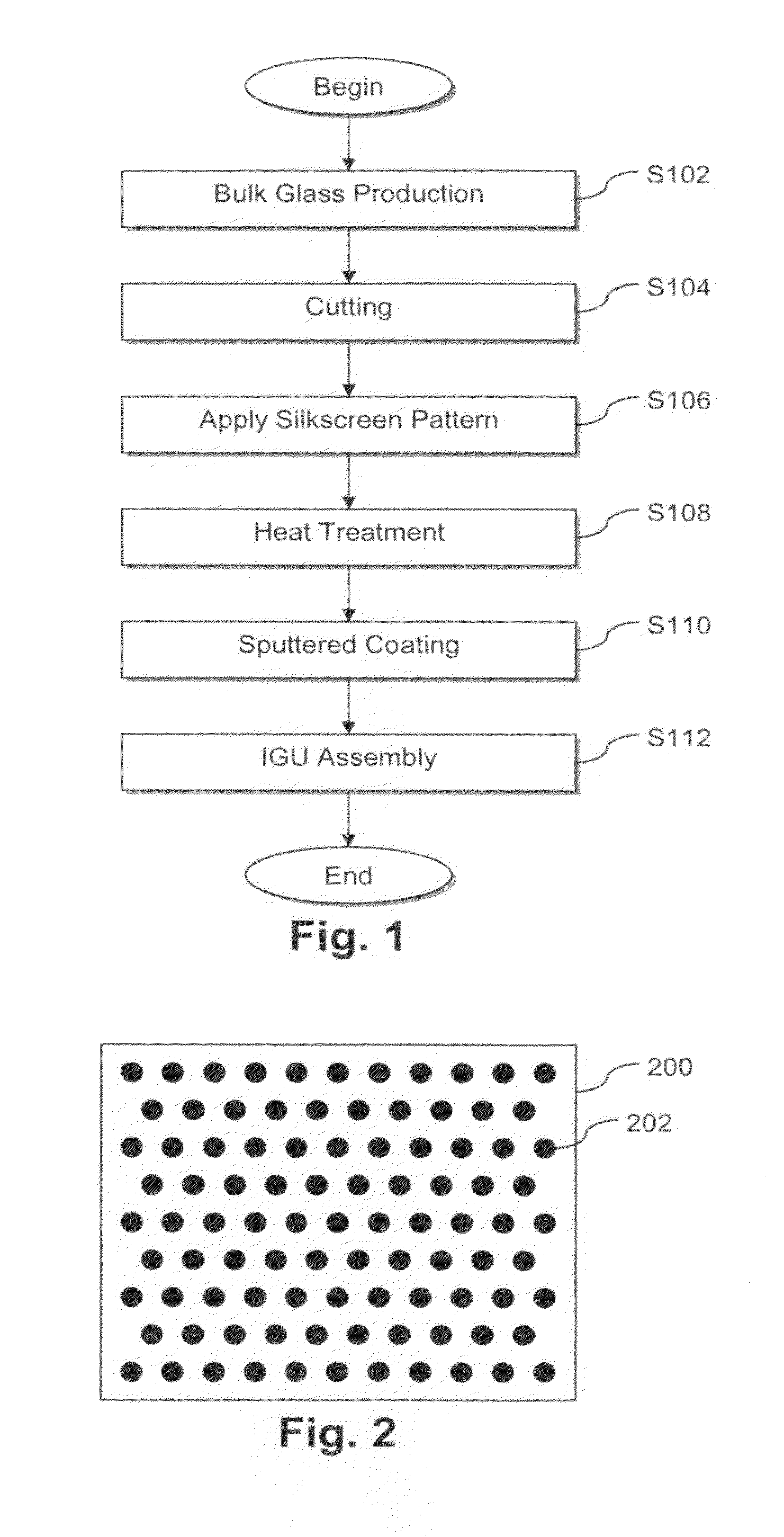
[0007]Unfortunately, the current process flow suffers from several inefficiencies and further improvements are desirable. For example, silkscreen and inkjet printing processes are performed on the cut substrates, prior to heat treatment. By contrast, thin film deposition is performed after the heat treatment, e.g., to help ensure the survivability of the coating. The patterning and thin film coating of cut sheets, however, introduces inefficiencies as compared to patterning and coating the large, stock sheets of glass. Yield may be reduced, and patterning and / or coating processes may be complicated by the need to deal with multiple different sizes of cut glass substrates.

Problems solved by technology

A separate drying and / or firing process may sometimes be used; however, having separate high temperature processes for firing the frit and for heat treating the patterned substrate may be undesirable from cost perspectives (e.g., in terms of equipment costs), as well as time perspectives (e.g., as delays may be caused by multiple high-temperature heating and subsequent cooling processes).
Unfortunately, the current process flow suffers from several inefficiencies and further improvements are desirable.
The patterning and thin film coating of cut sheets, however, introduces inefficiencies as compared to patterning and coating the large, stock sheets of glass.
Yield may be reduced, and patterning and / or coating processes may be complicated by the need to deal with multiple different sizes of cut glass substrates.

Method used


Image

  • Substrates or assemblies having directly laser-fused frits, and/or method of making the same
  • Substrates or assemblies having directly laser-fused frits, and/or method of making the same
  • Substrates or assemblies having directly laser-fused frits, and/or method of making the same

Examples


Embodiment Construction

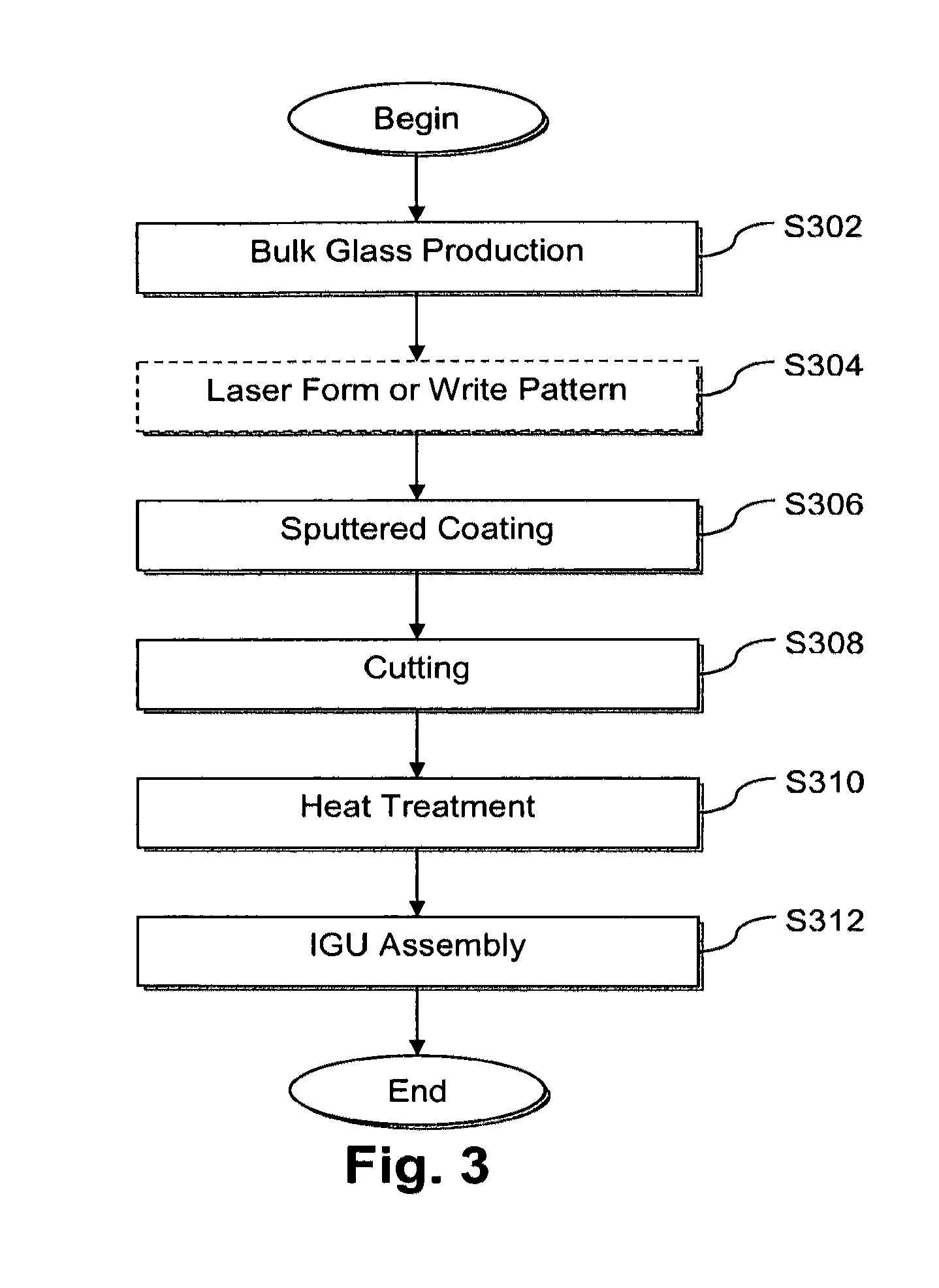
[0023]Certain example embodiments relate to substrates or assemblies having laser-fused frits, and / or methods of making the same. In certain example embodiments, (1) a pattern is formed or written on a stock glass sheet by laser fusing frit material to the glass sheet, (2) an optional thin film coating is disposed on and supported by the stock glass sheet, and (3) the stock glass sheet with the pattern and the optional thin film coating is cut prior to heat treatment (e.g., heat strengthening and / or thermal tempering). The laser fusing technique is fast and need not necessarily heat the entire substrate to the frit firing temperature. In other words, the laser may selectively heat a ceramic frit on the glass, either directly or indirectly. Thus, in certain example embodiments, a laser focused on the surface of the frit may help to fuse it to the glass without having to thermally treat the entire glass system. The glass substrate with the frit pattern thereon may still be in the anne...


PUM

PropertyMeasurementUnit
Fractionaaaaaaaaaa
Fractionaaaaaaaaaa
Frequencyaaaaaaaaaa

Abstract

Certain example embodiments relate to substrates or assemblies having laser-fused fits, and / or methods of making the same. In certain example embodiments, a pattern is formed or written on a stock glass sheet by laser fusing frit material to the glass sheet. An optional thin film coating is disposed on and supported by the stock glass sheet. The stock glass sheet with the pattern and the optional thin film coating is cut prior to heat treatment (e.g., heat strengthening and / or thermal tempering). A YAG or other type of laser source may be used to directly or indirectly heat the frit material, which may be wet applied to the substrate. In certain instances, the laser firing of the frit raises the temperature of the glass substrate to no more than 100 degrees C. and, preferably, the temperature is kept even lower.

Description

FIELD OF THE INVENTION[0001]Certain example embodiments of this invention relate to patterned substrates, and / or methods of patterning substrates. More particularly, certain example embodiments of this invention relate to substrates or assemblies having laser-fused fits, and / or methods of making the same. In certain example embodiments, (1) a pattern is formed or written on a stock glass sheet by laser fusing frit material to the glass sheet, (2) an optional thin film coating is disposed on and supported by the stock glass sheet, and (3) the stock glass sheet with the pattern and the optional thin film coating is cut prior to heat treatment (e.g., heat strengthening and / or thermal tempering).BACKGROUND AND SUMMARY OF EXAMPLE EMBODIMENTS OF THE INVENTION[0002]Ceramic frit patterns currently are applied to interior and exterior glass surfaces using known silkscreen or inkjet processes. These processes typically require the entire glass system to be heated to temperatures above 500 deg...

Claims


Application Information

Patent Timeline
IPC IPC(8): B32B17/06B32B3/10E06B3/66B23K26/00B05D3/06B23P11/00
CPCB23K26/0051B23K26/0063B23K26/0084C03C17/04Y10T428/24851C03C2217/72B44C1/00Y10T29/49885C03C17/34B23K26/0006B23K26/324B23K26/34B23K26/355B23K26/57B23K35/365B23K2101/34
Inventor WALP, MATTHEW S.
Owner GUARDIAN GLASS LLC
Learn More