Laser lap welding method

a lap welding and lap welding technology, applied in welding equipment, metal-working equipment, manufacturing tools, etc., to achieve the effect of increasing the space required for securing the welding length, preventing formation, and increasing the cycle tim

Inactive Publication Date: 2012-08-23
SUZUKI MOTOR CORP
View PDF21 Cites 24 Cited by
  • Summary
  • Abstract
  • Description
  • Claims
  • Application Information

AI Technical Summary

Benefits of technology

[0017]As described above, with the laser lap welding method according to the present invention, it is possible to reliably prevent the formation of a hole and an indentation at the welding terminating end while avoiding an increase in the space required for securing the welding length and an increase in the cycle time. Thus, the laser lap welding method according to the present invention is advantageous to improve the quality of laser lap welding.

Problems solved by technology

When the laser beam is irradiated again onto the metal portion once brought into a molten state by the laser welding, the metal in the molten state is scattered, so that burn-through, and the like, is caused.

Method used


Image

  • Laser lap welding method
  • Laser lap welding method
  • Laser lap welding method

Examples


example

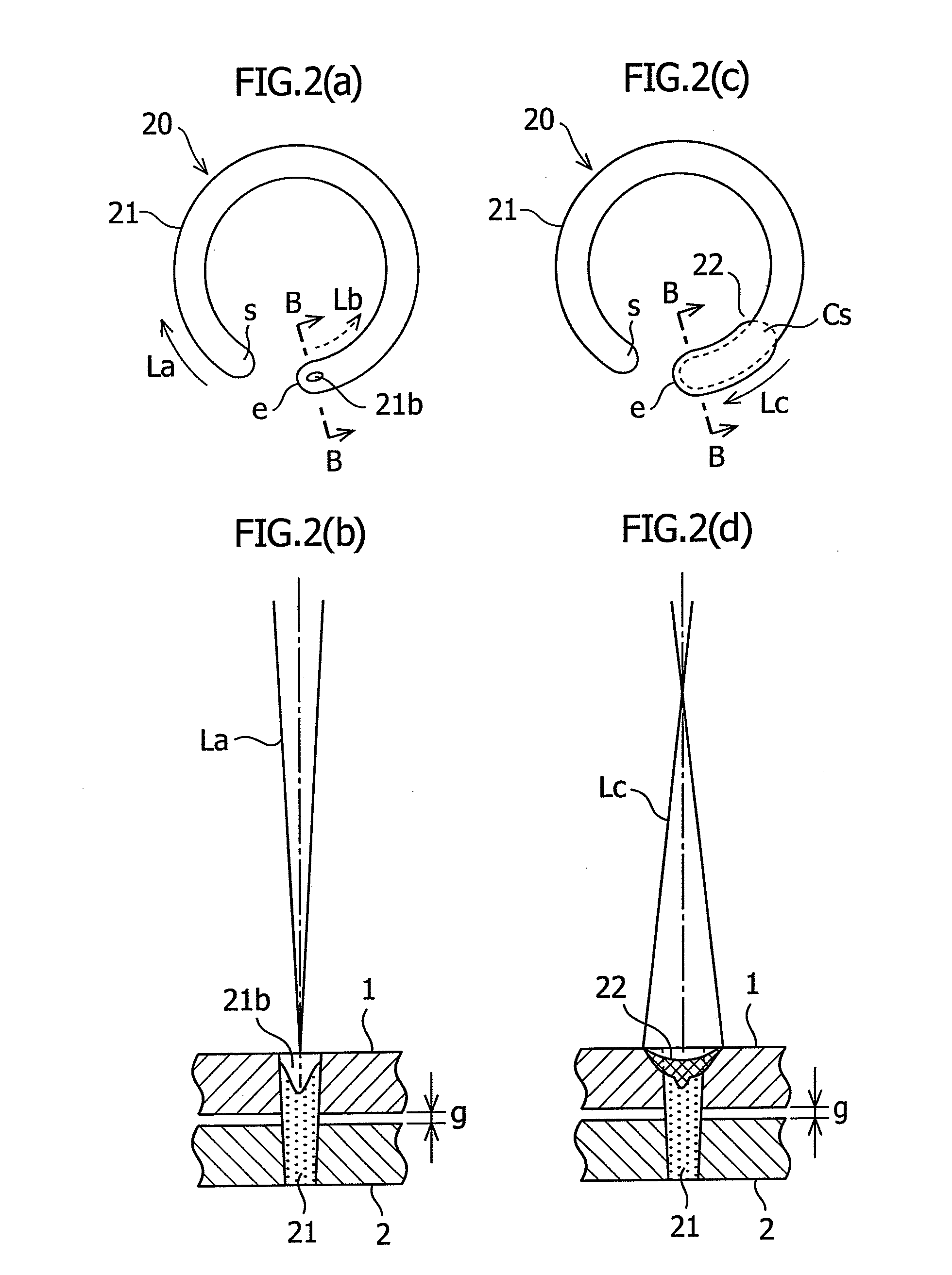
[0034]In order to verify the effect of the laser lap welding method according to the present invention, experiments were performed in the laser lap welding 20 according to the second embodiment described above, and the quality of the weld bead was evaluated by changing the defocus amount Dc of the laser irradiation Lc in a range of 15 to 50 mm in each of the cases of the gap g between workpieces being (a) g=0.2 mm, (b) g=0.1 mm, and (c) g=0.05 mm.

[0035]In the experiments, an optical fiber laser oscillator (having a maximum output: 7 kW, a diameter of transmission fiber: 0.2 mm) manufactured by IPG photonics company, and a scanner head (having a processing focal diameter in the focused state: 0.6 mm) manufactured by HIGHYAG laser technology company were used.

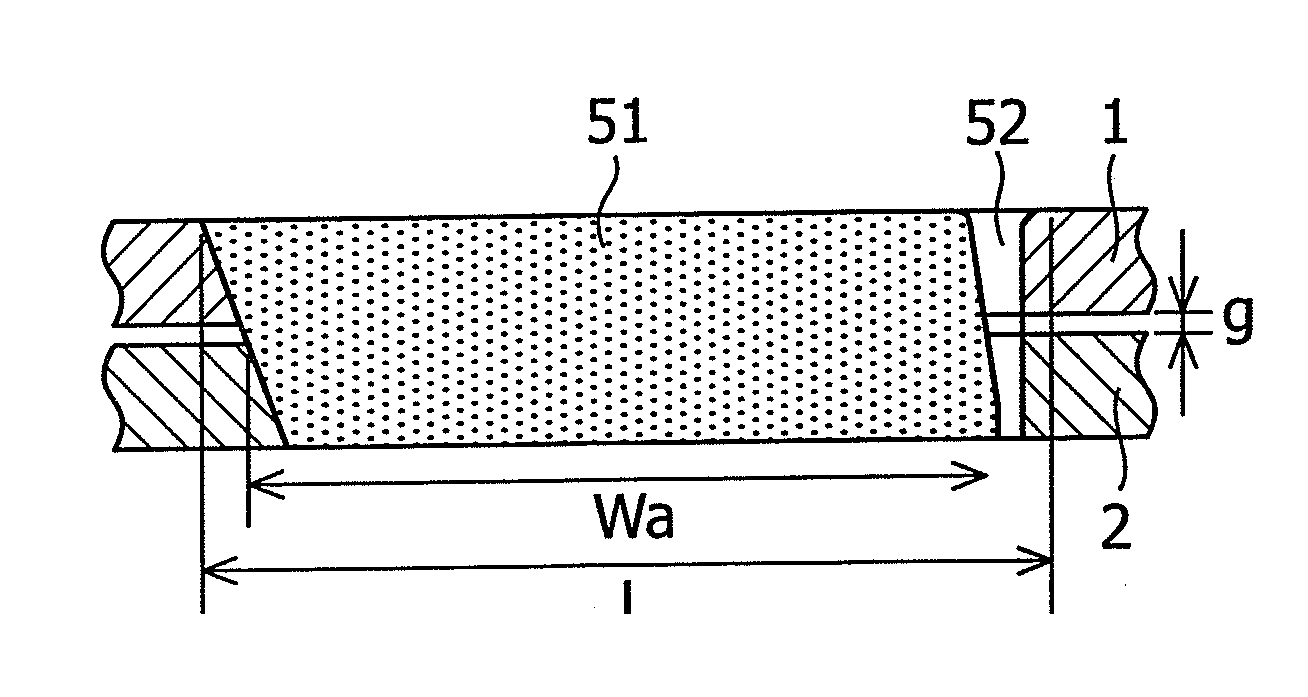
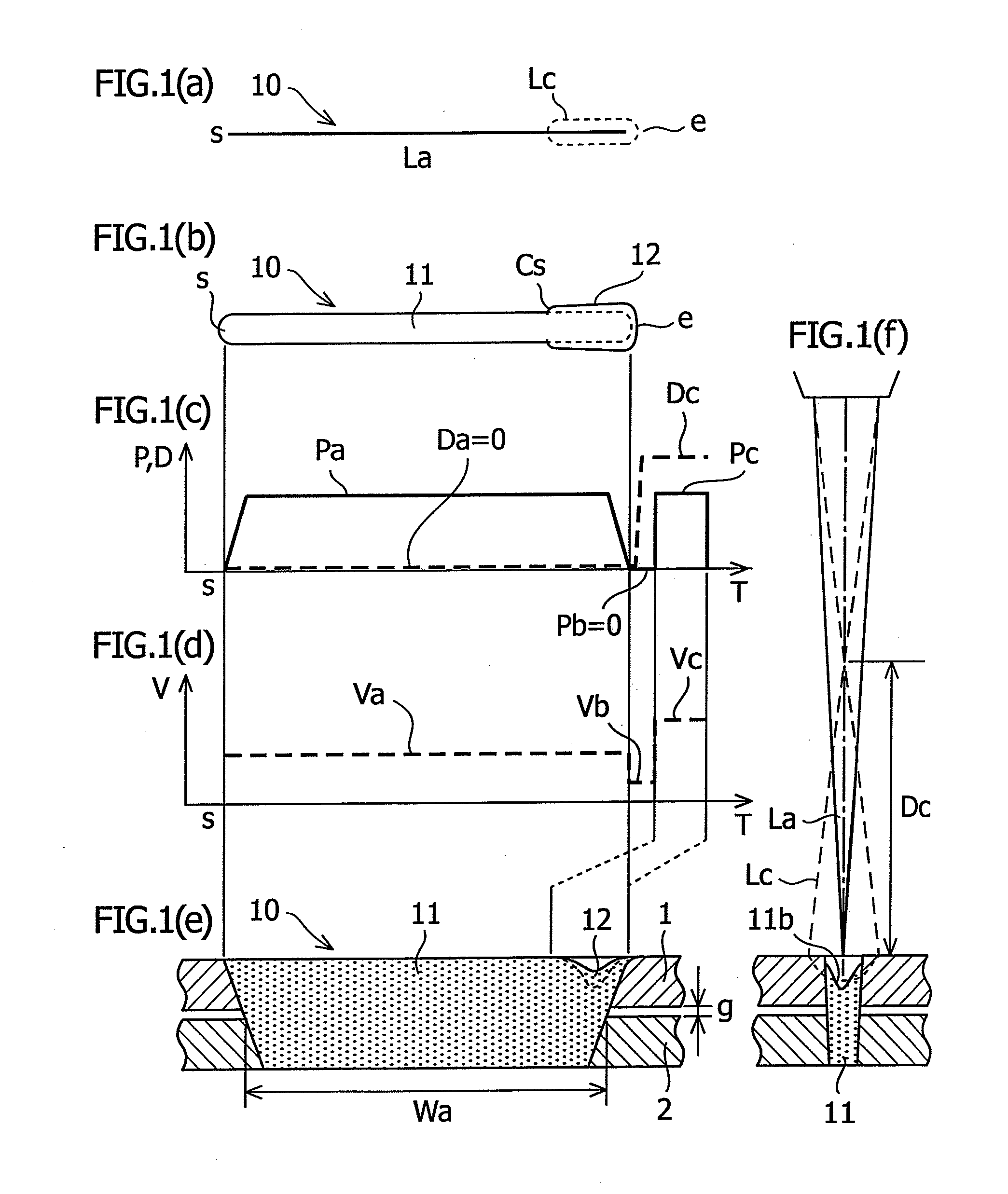
[0036]In each of the states in which, as a workpiece, a non-plated steel sheet (1) having a thickness of 0.65 mm was overlapped on a galvanized steel sheet (2) having a thickness of 0.8 mm with the above-described gaps g, when th...


PUM

PropertyMeasurementUnit
timeaaaaaaaaaa
indentation depthaaaaaaaaaa

Abstract

To provide a laser lap welding method including: performing lap welding (11; 21) by irradiating a laser beam (La) on a plurality of overlapped workpieces (1, 2); and irradiating, after a very short interruption time period of the laser beam irradiation, a defocused laser beam (Lc) on a terminating end (12; 22) of the lap welding. Preferably, the laser lap welding method including: interrupting the irradiation of the laser beam for a very short time period and moving, during the interruption time period, the optical axis of the laser beam from the terminating end of the lap welding to the side of the starting end of the lap welding; and irradiating a defocused laser beam from the position to which the optical axis of the laser beam is moved, to the terminating end of the lap welding.

Description

CROSS-REFERENCE TO RELATED APPLICATIONS[0001]The present application claims priority to Japanese Patent Application No. 2011-036174, filed Feb. 22, 2011, which is incorporated herein in its entirety.FIELD OF THE INVENTION[0002]The present invention relates to a laser lap welding method, and more particularly to a laser lap welding method which improves a hole, an indentation, and the like, that are caused at a welding terminating end.BACKGROUND OF THE INVENTION[0003]A laser welding method, in which a laser beam is irradiated onto a workpiece to heat and melt a material of the irradiated portion by the light energy of the laser beam, has an advantage in that high speed welding can be performed in a non-contact manner, but has a problem in that a hole and an indentation are caused at a welding terminating end. Thus, this problem has become one of the factors that limit the use of the laser welding method to only some automobile parts and prevents the laser welding method from being us...

Claims


Application Information

Patent Timeline
Patent Type & Authority Applications(United States)
IPC IPC(8): B23K26/24B23K26/06B23K26/21
CPCB23K26/0665B23K26/28B23K26/246B23K26/244
Inventor HAYASHIMOTO, KAZUHIROFUJINUMA, YUTAHAGIHARA, TSUKASASANUKI, YOSHITAKA
Owner SUZUKI MOTOR CORP
Why Eureka
Try Eureka