Magneto-resistive effect element having spacer layer including main spacer layer containing gallium oxide and metal intermediate layer

a technology of magnetoresistive effect and metal intermediate layer, which is applied in the field of spacer layer configuration, can solve the problems of reducing the reliability of the magnetic head and unable to produce sufficient antioxidation effects with the copper layer

Active Publication Date: 2012-08-23
TDK CORPARATION
View PDF4 Cites 3 Cited by
  • Summary
  • Abstract
  • Description
  • Claims
  • Application Information

AI Technical Summary

Benefits of technology

[0011]In the meantime, as described above, the magnetic layers adjacent to the spacer layer are normally composed of Co, Nr, Fe and the like as a primary component. Therefore, when these elements are positioned in a manner of contacting gallium oxide, the magnetic layers are oxidized due to an oxidation action of oxygen contained in gallium oxide, and thereby an MR ratio may be decreased. Specifically, gallium oxide may oxidize the elements configuring the first magnetic layer since oxygen contained in gallium oxide is diffused. Thereby, polarizability may be decreased and the MR ratio may be lowered. This phenomenon, that is, a diffusion phenomenon of oxygen contained in gallium oxide, is more likely to occur especially under high temperature. A heating process may be performed on the MR element after a lamination film is formed, and the decrease in the MR ratio due to the oxidation of the first magnetic layer may become remarkable when the heating process is performed. Also, since the inside of the hard disk drive is often operated under high temperature environment, the oxidation of the first magnetic layer may contribute to decrease the reliability of the magnetic head.
[0012]Accordingly, in the present invention, a portion of the spacer layer is configured with a copper layer. The copper layer has an effect to prevent the diffusion of oxygen contained in gallium oxide and also an effect to adjust a resistance area (RA) in an appropriate value. However, as described above, sufficient antioxidation effects cannot be produced only with the copper layer especially under a high temperature environment.
[0013]Therefore, in the present invention, a metal intermediate layer is provided between the copper layer and the main spacer layer composed of gallium oxide as a primary component. The metal intermediate layer is composed of at least one member selected from a group consisting of one of magnesium and at least partially oxidized magnesium, one of aluminum and at least partially oxidized aluminum, and one of zinc and at least partially oxidized zinc, as a primary component. Compared to Co, Ni and Fe that configure the first magnetic layer, magnesium, aluminum and zinc have a lower standard electrode potential and are more likely to be oxidized than Co, Ni and Fe. Therefore, even in a partially-oxidized state as well as in a metal state, these elements trap oxygen and prevent oxygen from reaching to the first magnetic layer. While magnesium, aluminum and zinc themselves become metal oxides as described above and cooperate with the copper layer, further enhanced oxygen diffusion prevention effect can be provided.

Problems solved by technology

Also, since the inside of the hard disk drive is often operated under high temperature environment, the oxidation of the first magnetic layer may contribute to decrease the reliability of the magnetic head.
However, as described above, sufficient antioxidation effects cannot be produced only with the copper layer especially under a high temperature environment.

Method used


Image

  • Magneto-resistive effect element having spacer layer including main spacer layer containing gallium oxide and metal intermediate layer
  • Magneto-resistive effect element having spacer layer including main spacer layer containing gallium oxide and metal intermediate layer
  • Magneto-resistive effect element having spacer layer including main spacer layer containing gallium oxide and metal intermediate layer

Examples


first embodiment

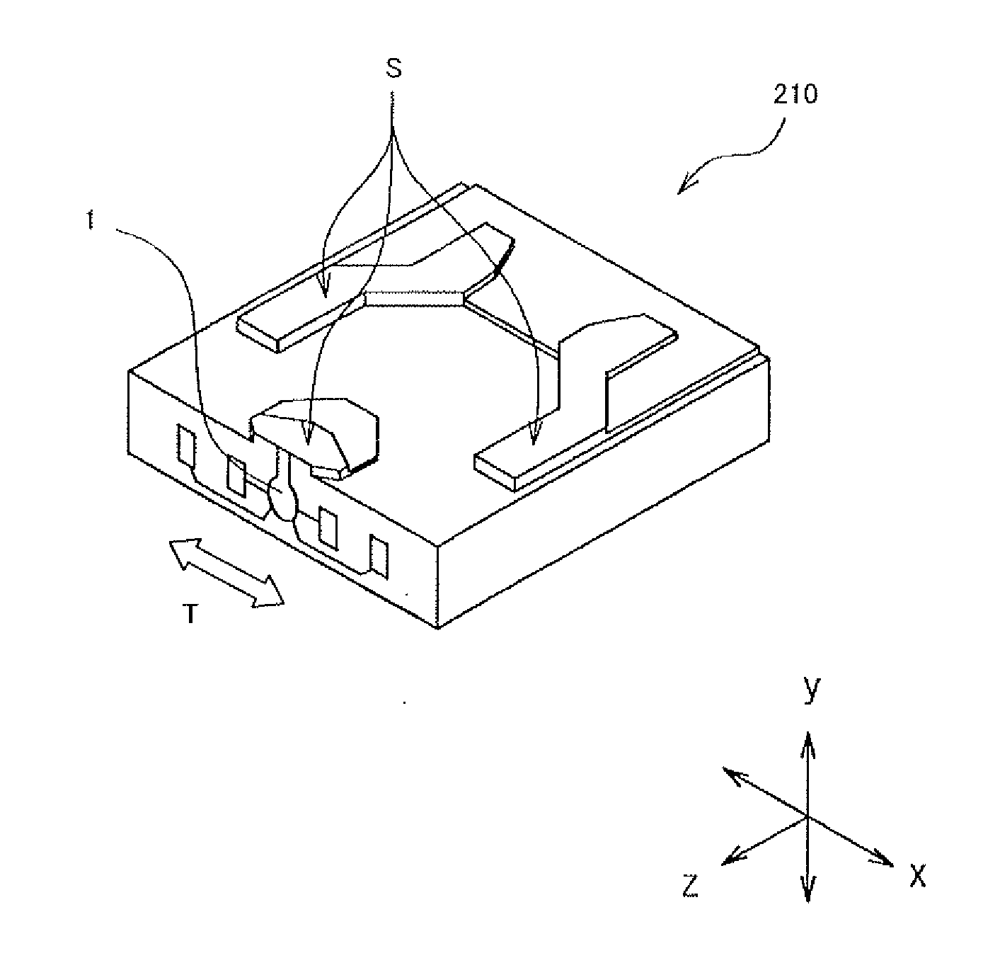
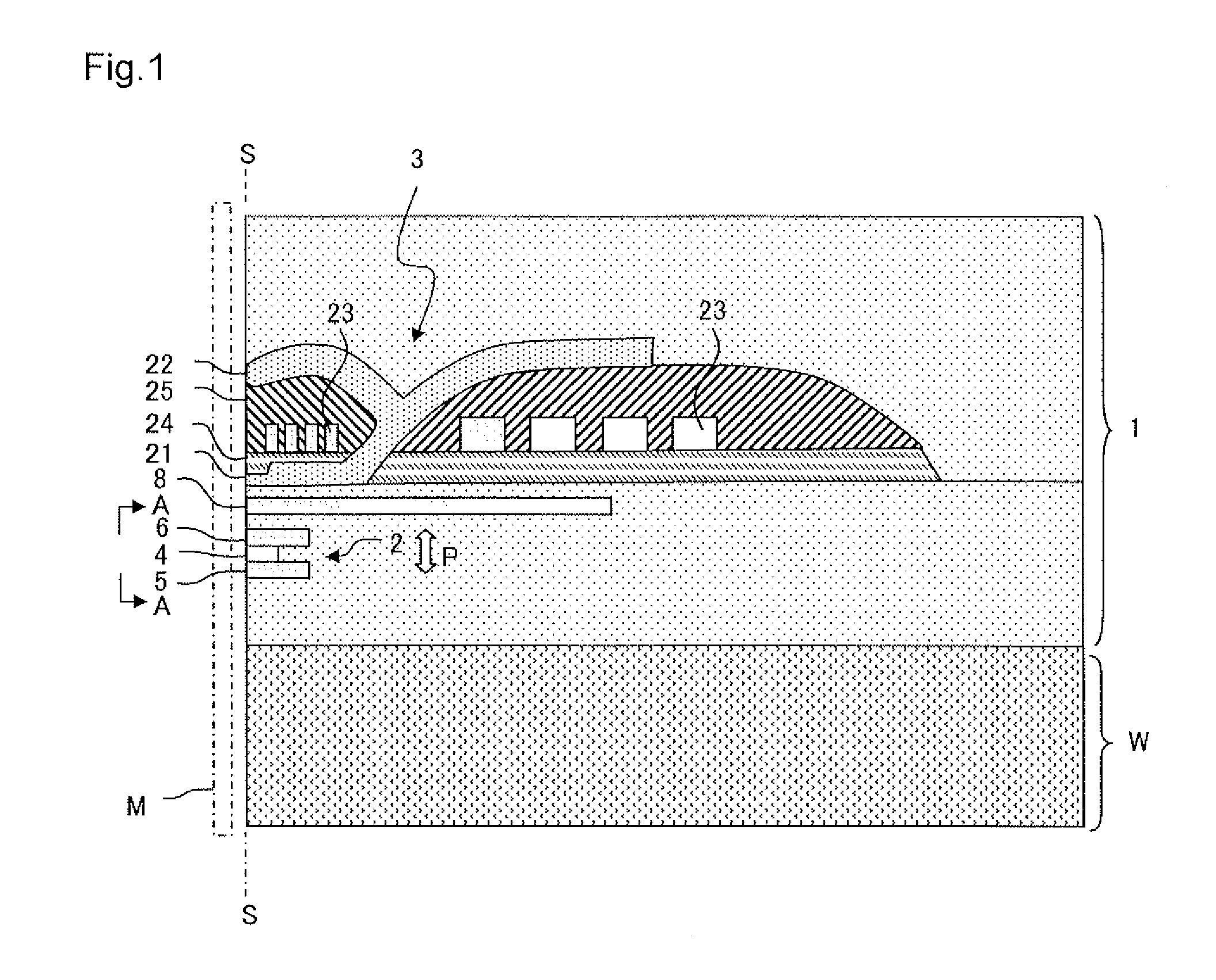
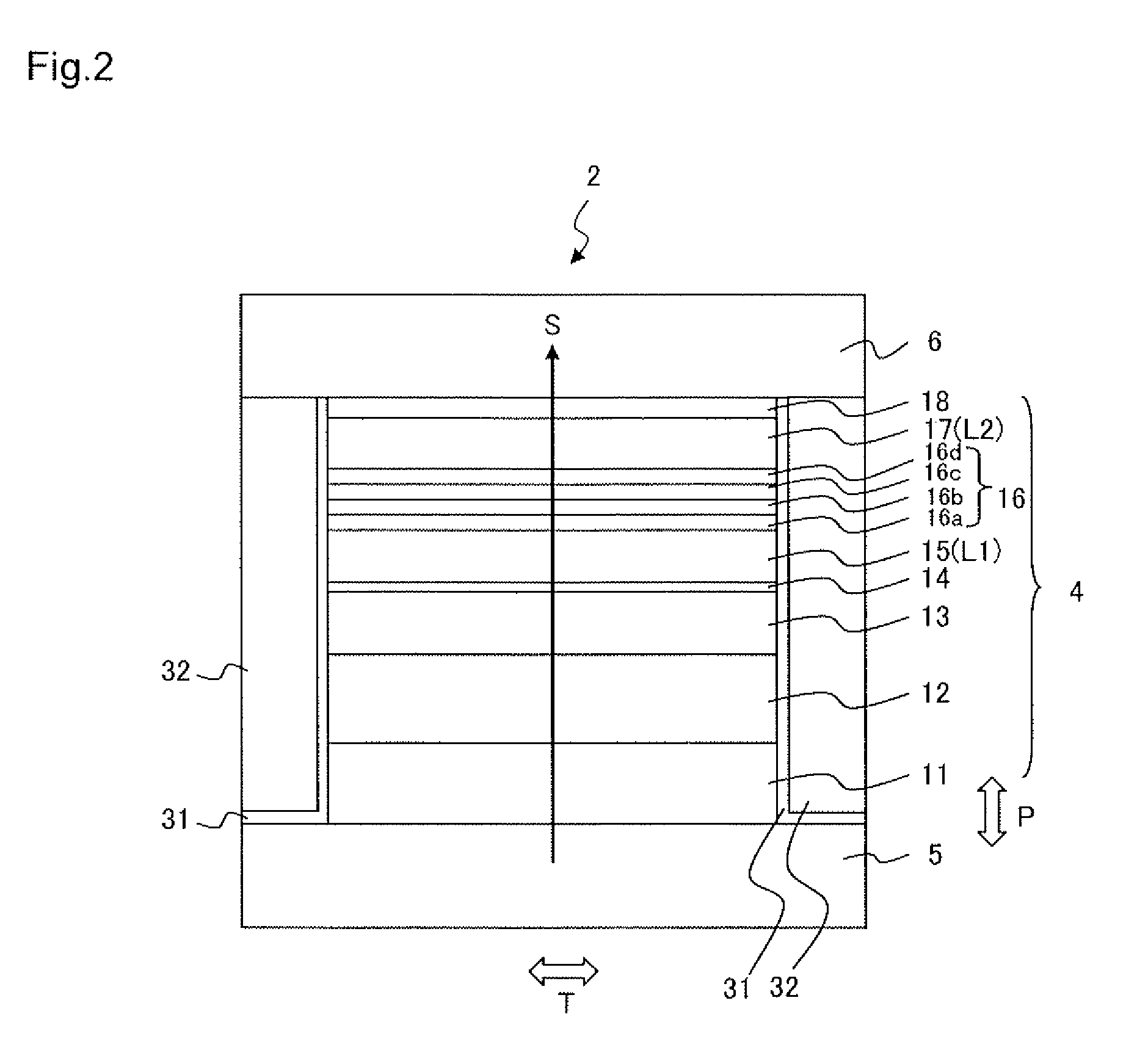
[0024]FIG. 1 illustrates a main part cross-sectional view of a thin film magnetic head 1 according to a first embodiment. The thin film magnetic head 1 is formed on a substrate W and includes a reproducing head 2 and a recording head 3. FIG. 2 illustrates a side view of the reproducing head 2 as viewed from the A-A direction in FIG. 1, that is, a layer configuration on an air bearing surface S of the reproducing head 2. The air bearing surface S is a surface of the thin film magnetic head 1 that opposes a recording medium M. First, a description will be given regarding a configuration of the reproducing head 2 with reference to FIG. 2.

[0025]The reproducing head 2 includes a spin valve type MR element 4, upper and lower shield layers 6 and 5 disposed in a manner of sandwiching the MR element 4 in a film surface orthogonal direction (lamination direction) P, and bias magnetic field application layers 32 disposed on both sides in the track width direction T of the MR element 4 (directi...

second embodiment

[0048]A thin film magnetic head 1 of the present embodiment is the same as the first embodiment illustrated in FIG. 1 with the exception of the configuration of the reproducing head 2. FIG. 3 and Table 2 illustrate a layer configuration of such an MR element. A reproducing head 102 includes an MR element 104 in which a large number of layers are laminated in the same manner as the first embodiment, and upper and lower shield layers 106 and 105 that are disposed so as to sandwich the MR element 104 in the film surface orthogonal direction P (lamination direction). The upper and lower shield layers 106 and 105 are also used as electrodes for the sense current S so that the sense current S flows in the film surface orthogonal direction P of the MR element 104.

[0049]With the present embodiment, the first magnetic layer L1 and the second magnetic layer L2 are magnetization free layers 115 and 117, respectively, in which the magnetization direction changes in response to the external magn...

first example

[0062]An MR element with the film configuration illustrated in Table 2 was formed above a substrate composed of Al2O3—TiC (ALTIC) by using a sputtering device. A film configuration of a spacer layer was as indicated in Table 4. A gallium oxide layer was formed by a radio frequency (RF) sputtering method, and the other films were formed by a direct current (DC) magnetron sputtering method. At the time of forming the spacer layer, an Mg film, Al film or Zn film in metal state was formed on a copper layer. Accordingly, this table and Tables 5 and 6 indicate a metal layer instead of a metal intermediate layer. After the film formation, thermal (annealing) treatment was performed at 250° C. for three hours, and the MR element having a junction size of 0.2 μm×0.2 μm was manufactured. After the formation of the MR element, no annealing was performed. When no external magnetic field is applied, the directions of the first and second magnetization free layers are oriented orthogonally to eac...


PUM

PropertyMeasurementUnit
thicknessaaaaaaaaaa
thicknessaaaaaaaaaa
mole fractionaaaaaaaaaa

Abstract

A magneto-resistive effect (MR) element includes first and second magnetic layers in which a relative angle formed by magnetization directions changes in response to an external magnetic field, and a spacer layer positioned between the first magnetic layer and the second magnetic layer. The first magnetic layer is positioned closer to a substrate above which the MR element is formed than the second magnetic layer. The spacer layer includes a copper layer, a metal intermediate layer and a main spacer layer composed of gallium oxide as a primary component. The copper layer and the metal intermediate layer are positioned between the main spacer layer and the first magnetic layer. The metal intermediate layer is positioned between the copper layer and the main spacer layer. The metal intermediate layer is composed of at least one member selected from a group consisting of one of magnesium and at least partially oxidized magnesium, one of aluminum and at least partially oxidized aluminum, and one of zinc and at least partially oxidized zinc, as a primary component.

Description

BACKGROUND OF THE INVENTION[0001]1. Field of the Invention[0002]The present invention relates to a magneto-resistive effect (MR) element and a manufacturing method thereof, and particularly relates to a configuration of a spacer layer.[0003]2. Description of the Related Art[0004]Reproducing heads with high sensitivity and high output are in demand in conjunction with condensing of high recording density in hard disk drives (HDD). As an example of this type of reproducing head, a spin valve head has been developed. A spin valve head includes a nonmagnetic metal layer and a pair of ferromagnetic layers positioned on both sides of the nonmagnetic metal layer in a manner of contacting the nonmagnetic metal layer. The magnetization direction of one of the ferromagnetic layers is pinned in one direction (hereinafter, this type of layer is referred to as a magnetization pinned layer), and the magnetization direction of the other one of the ferromagnetic layers freely rotates in response to...

Claims


Application Information

Patent Timeline
Patent Type & Authority Applications(United States)
IPC IPC(8): G11B5/48G11B5/39G11B5/127G11B21/24
CPCG01R33/093G11B5/3929Y10T29/49032G11B5/3906B82Y25/00Y10T428/1121G11B2005/3996B82Y10/00
Inventor TSUCHIYA, YOSHIHIROCHOU, TSUTOMUMATSUZAWA, HIRONOBUKOIKE, HAYATO
Owner TDK CORPARATION
Why Eureka
Try Eureka