
Methods and systems for noise resilient, pin-efficient and low power communications with sparse signaling codes

a signaling code and low power technology, applied in the field of communication, can solve the problems of large memory impact on battery life, inability to design high-speed, low-power and pin-efficient chip-to-chip communication systems, and inability to meet the requirements of communication channels, so as to reduce the amount of energy needed

Active Publication Date: 2012-08-23
ECOLE POLYTECHNIQUE FEDERALE DE LAUSANNE (EPFL)
View PDF3 Cites 159 Cited by
  • Summary
  • Abstract
  • Description
  • Claims
  • Application Information

AI Technical Summary

Benefits of technology

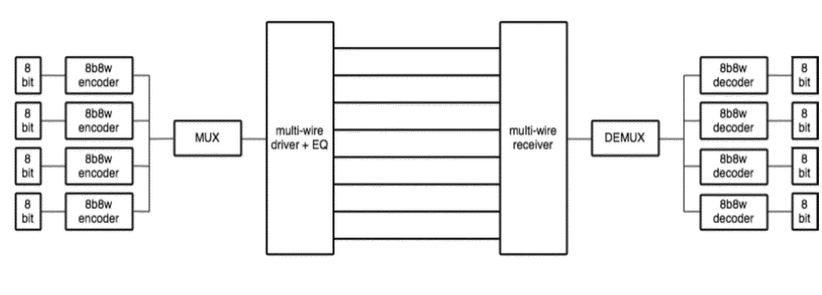
[0022]In a particular embodiment, information is transmitted over a communication bus by receiving a first set of signals representing the information, mapping the first set of signals to a second set of signals, wherein the second set of signals comprises one or more code word selected from among the valid code words of a sparse signaling code, and providing the second set of signals for transmission over the communication bus. A corresponding decoder decodes the second set of signals (possibly altered by the communication bus) in an attempt to recover a replication of the first set of signals while reducing the amount of energy needed to do so.

Problems solved by technology

A battery feeds a mobile device and the power consumption of the communication between the CPU and memory has a large impact on the battery life.
The difficulty in designing high speed, low power and pin-efficient chip-to-chip communication systems lies in part in the fact that the communication channel is not perfect.
First, the physical wires will disturb the signals transmitted on them and noise and interference will be added to the transmitted signals.
Second, the electronic components used to implement the communication system are not perfect and this disturbs the signals used for communication.
There are several typical sources of noise in chip-to-chip communication systems.
First, there is noise and interference that is common to a set of wires.
Second, there is thermal noise that is induced in electrical conductors.
Third, there is simultaneous switching output (“SSO”) noise that is caused by a time-varying current in the electronics that drive the wires.
Fourth, the signals transmitted on different wires may interfere with one other, which causes crosstalk and severely degrades signal integrity especially at high speeds.
Such references are hard to make precisely and any errors in the reference may cause unwanted distortions and noise.
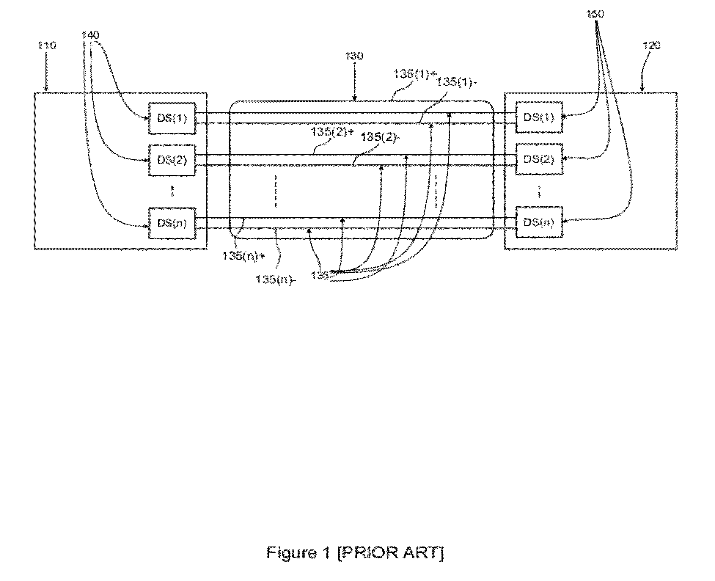
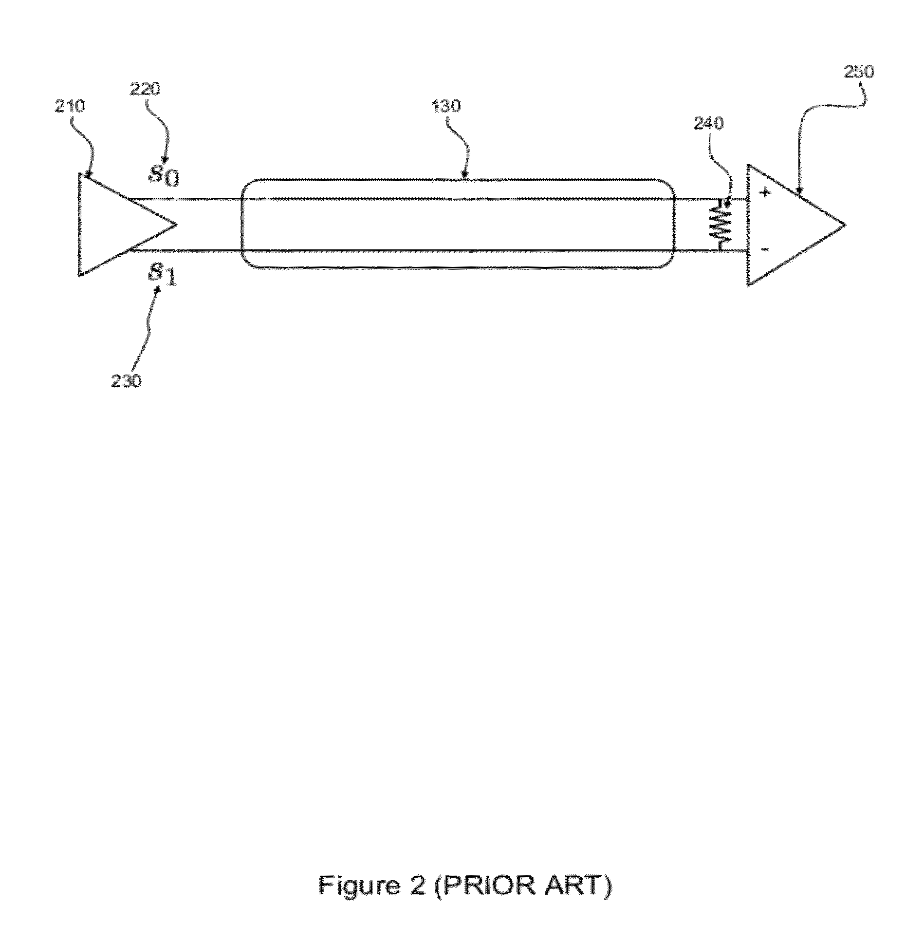
A major disadvantage of differential signaling is that it requires two wires for every signal that is to be transmitted on the communication bus.
Furthermore, a substantial amount of transmitter power is required to operate a bus communication system based on differential links.
However, the resulting pin-efficiencies are substantially less than one and the methods disclosed in [Chiarulli] only lead to moderate improvements in power consumption.
Furthermore, encoding and decoding complexity is an issue for the methods disclosed in [Chiarulli].
However, a major downside of the methods disclosed in [Poulton] is the complexity of the circuitry required for encoding and decoding at the transmitter and receiver side.
Furthermore, the scheme does not lead to improvements in power consumption and is only useful to improve upon the pin-efficiency, as pointed out in [Poulton].

Method used


Image

  • Methods and systems for noise resilient, pin-efficient and low power communications with sparse signaling codes
  • Methods and systems for noise resilient, pin-efficient and low power communications with sparse signaling codes
  • Methods and systems for noise resilient, pin-efficient and low power communications with sparse signaling codes

Examples


Embodiment Construction

[0070]FIG. 3 is a high-level block diagram of a bus communication system over which the present invention might be used, or conventional transmitters / receivers might be used. With such a system, there are multiple wires of the bus and signals are sent over those multiple wires, typically at a periodic rate. Thus, an information source 310 might provide a sequence of k information symbols per period, where the period might be measured as a time interval of 1 / T seconds. In preferred embodiments, T is greater than one and where T is an integer, the bus can convey the information content of kT symbols per second. Without loss of generality, we can assume that these information symbols are bits.

[0071]These bits are to be transmitted on the communication bus 130 to a destination 350. The communication bus 130 comprises n physical wires 135. An example of such a communication bus 130 is for example a bus between a processor and memory. In this case the physical wires may take the form of s...


PUM


Abstract

In bus communications methods and apparatus, a first set of physical signals representing the information to be conveyed over the bus is provided, and mapped to a codeword of a sparse signaling code, wherein a codeword is representable as a vector of a plurality of components, some of which are quiescent components and some of which are non-quiescent components, wherein the number of quiescent components and non-quiescent components meet a sparseness requirement.

Description

CROSS REFERENCES[0001]The following references are herein incorporated by reference in their entirety for all purposes:[0002]U.S. Patent Application No. 61 / 330,107 filed Apr. 30, 2010 naming Harm Cronie and Amin Shokrollahi, and entitled “Orthogonal Differential Vector Signaling” and hereinafter “Cronie I”).[0003]U.S. patent application Ser. No. 12 / 982,777 filed Dec. 20, 2010 naming Harm Cronie and Amin Shokrollahi, and entitled “Power and Pin Efficient Chip-to-Chip Communications with Common-Mode Rejection and SSO Resilience” (hereinafter “Cronie II”).FIELD OF THE INVENTION[0004]The present invention relates to communications in general and in particular to transmission of signals capable of conveying informationBACKGROUND OF THE INVENTION[0005]One goal of a communication system is to transport information from one physical location to another. In most electronic communication systems, the communication itself takes place between electronic components. Often, these electronic compo...

Claims


Application Information

Patent Timeline
IPC IPC(8): H04L27/00
CPCH04L1/0041H04L1/0045H04L1/0057H04J13/0003H04L2001/0094H03M7/3062G06F13/38H04L25/4908H04L1/00H04L25/08
Inventor CRONIE, HARMSHOKROLLAHI, AMINTAJALLI, ARMIN
Owner ECOLE POLYTECHNIQUE FEDERALE DE LAUSANNE (EPFL)
Learn More