Combustion of co and combustibles in steel furnace offgases

a technology of steel furnace and offgas, which is applied in the direction of furnace, separation process, manufacturing converter, etc., can solve the problems of eaf operators still operating problems, small amounts of co in the off-gas (called “co slip”), and the inability to recover other combustibles, etc., to achieve jet momentum, reduce the effect of low concentration level and enhancing the ability of radicals

Inactive Publication Date: 2012-08-23
WU KUANG TSAI +1
View PDF6 Cites 5 Cited by
  • Summary
  • Abstract
  • Description
  • Claims
  • Application Information

AI Technical Summary

Benefits of technology

[0012](C) feeding the hot oxygen stream formed in step (B) into the offgas stream provided in step (A) to raise the temperature of the offgas in said provided stream to a temperature higher than 1100F that is higher than the temperature of the offgas to which said hot oxidant stream is added, wherein the hot oxygen stream is added at a rate sufficient to convert carbon monoxide in the offgas to which it is added to carbon dioxide, thereby lowering the carbon monoxide content of said offgas.
[0015]This invention involves injecting a stream or streams of high-momentum hot oxygen to destroy low concentration levels of off-gas combustibles, particularly where the off-gas temperature is already below the spontaneous ignition temperature of the off-gas combustibles. Because the injected oxygen is hot and the jet momentum is high, the hot oxygen will mix rapidly with the offgas, thus enhancing the ability of the radicals in the hot oxygen stream to destroy combustibles in the offgas even though the offgas temperature is below the combustibles' ignition temperatures. These streams of high momentum hot oxygen are produced by the hot oxygen generator described herein.

Problems solved by technology

If scrap preheating is not used then once the off-gas leaves the EAF vessel, the remaining energy contained in the unburned CO, H2, and other combustibles may or may not be recovered.
Despite the above efforts, the presence of small amounts of CO in the off-gas (termed “CO slip”) is still an operational issue for many EAF operators.
These variations in off-gas properties are further complicated by the varying amount of the air infiltration and the changing composition of the scrap being fed.
Thus, keeping the bag house CO emissions in check during the whole EAF heat cycle represents challenges to the furnace operators.
EAF operators face heavy financial penalties should the CO emissions exceed regulatory limits.
In order to avoid exceeding emissions limits for CO and other combustibles, some EAF operators may opt to operate their furnaces conservatively in order to meet the emissions limits, but at the expense of furnace energy efficiency.
For example, an operator may set the furnace or the exhaust duct pressures low to induce excessive amount of air infiltration for completing CO burnout.
This excess amount of air can increase the total flue gas volume and the heat loss associated with the off-gas, thus decreasing the furnace thermal efficiency.
In other instances, the production capacity of an EAF furnace can be substantially limited by the ability of the downstream ducts or dropout box to complete the combustion of the CO, H2, and other combustibles.
If scrap preheating is used, EAF operators may also face the issue of containing fugitive odors and limiting the formation of undesired byproducts such as dioxins in the flue gas ducts.

Method used


Image

  • Combustion of co and combustibles in steel furnace offgases
  • Combustion of co and combustibles in steel furnace offgases
  • Combustion of co and combustibles in steel furnace offgases

Examples


Embodiment Construction

[0022]While the following description of the present invention refers to the Figures, the invention is not to be considered to be confined to the embodiments illustrated in the Figures.

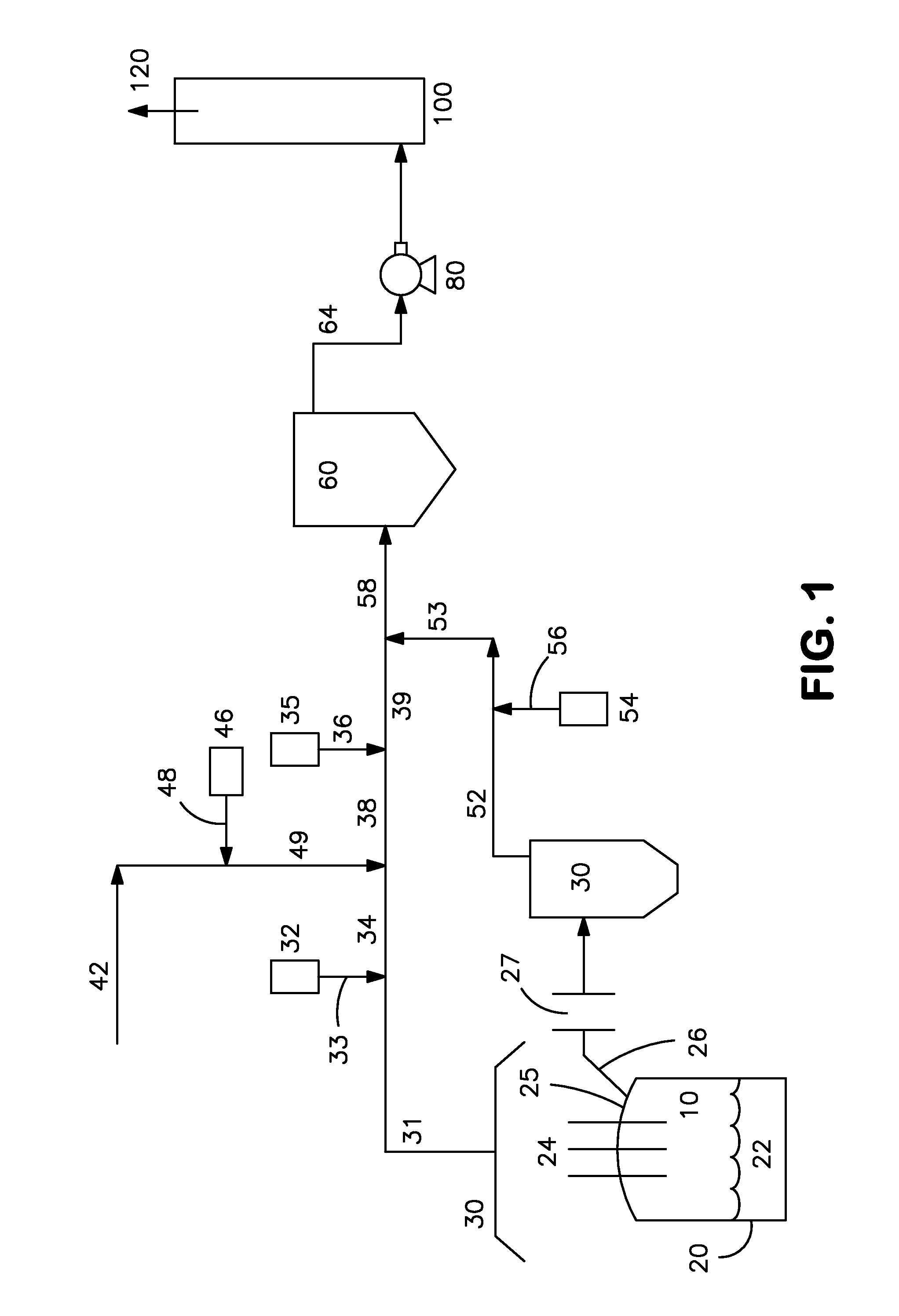
[0023]FIG. 1 illustrates several different possible applications of this invention to control CO emissions from steelmaking furnaces. Any one or more of these applications can be practiced, separately or as an overall system for controlling CO emissions.

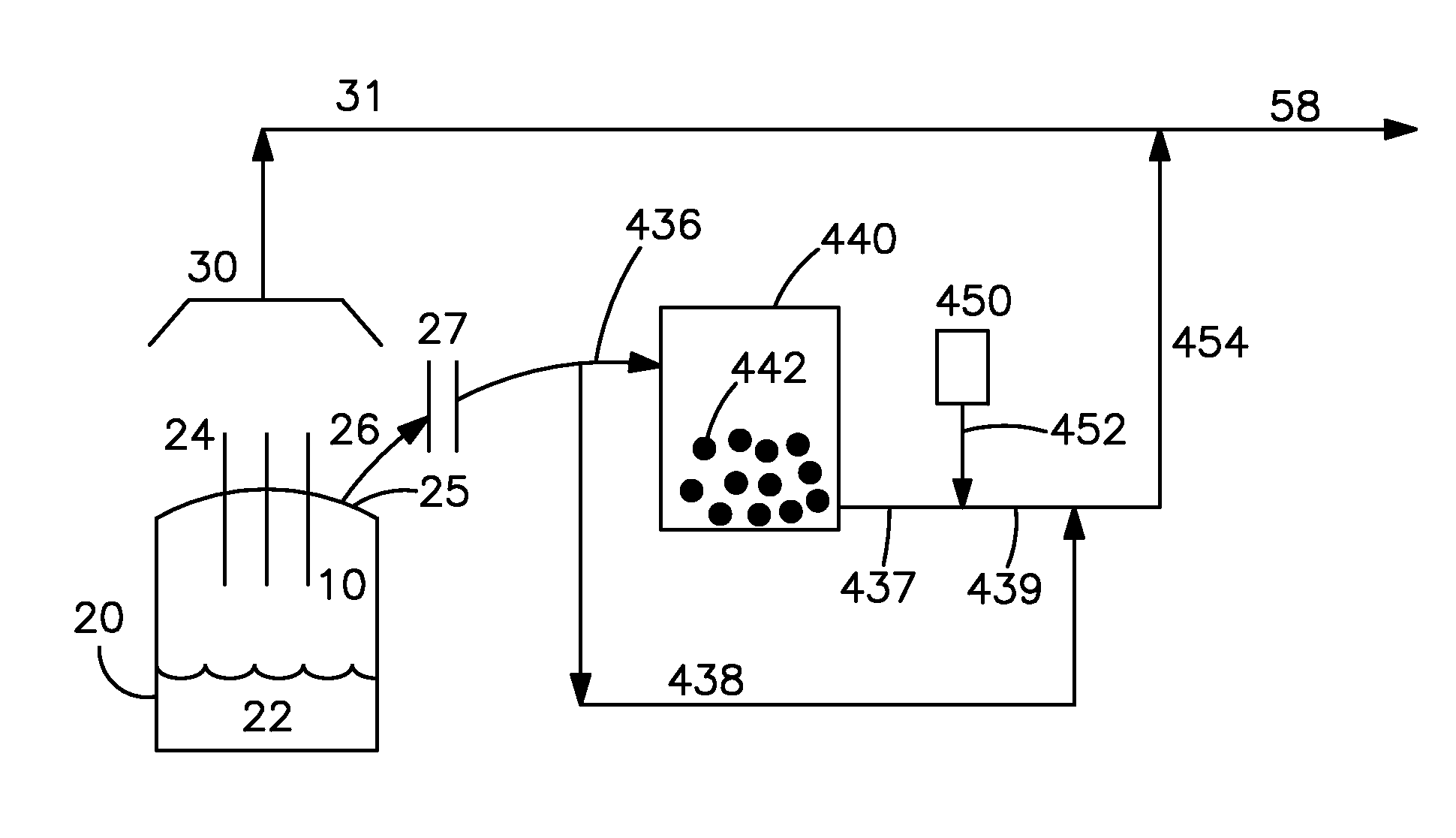
[0024]Referring to FIG. 1, offgas 10 is generated in an electric arc furnace (“EAF”) 20 which has electrodes 24 over molten steel 22. While three electrodes 24 are shown, other numbers of electrodes can be employed, and the EAF can be operated with alternating current or direct current. The offgas stream 10 flows through an outlet (sometimes referred to as a “4th hole”) 25 into a conduit (or duct) 26, and then through air gap 27 which is an opening in duct 26 through which air from the surrounding atmosphere can enter into duct 26. Air is admitted into...


PUM

PropertyMeasurementUnit
velocityaaaaaaaaaa
velocityaaaaaaaaaa
pressureaaaaaaaaaa

Abstract

A hot oxygen stream containing radicals is fed into an offgas stream from a steelmaking vessel to convert carbon monoxide in the offgas to carbon dioxide.

Description

CROSS-REFERENCES TO RELATED APPLICATIONS[0001]This application is a continuation of and claims priority from U.S. application Ser. No. 12 / 602,627 filed Dec. 21, 2009, which was a National Stage Entry of application PCT / US09 / 48211, filed Jun. 23, 2009, which claims priority from U.S. Provisional Patent Application No. 61 / / 075,958, filed Jun. 26, 2008, which is hereby incorporated herein by reference.FIELD OF THE INVENTION[0002]This invention relates to treatment of offgas streams produced by steel furnaces.BACKGROUND OF THE INVENTION[0003]During steel production in an electric arc furnace (EAF) a large volume of high temperature off-gas, which contains high concentrations of combustible gases such as carbon monoxide (CO) and hydrogen (H2), is produced inside the EAF vessel. This off-gas can reach a temperature of 3000 F or higher, and CO and H2 peak concentrations in the off-gas can reach up to 60% and 35%, respectively. To reduce electrical energy consumption, the thermal energy con...

Claims


Application Information

Patent Timeline
Patent Type & Authority Applications(United States)
IPC IPC(8): B01D53/62
CPCB01D53/62B01D2257/502C21C5/305Y02C10/04C21C5/527C21C2100/02F27D17/008C21C5/5211Y02P10/122Y02A50/20Y02C20/40Y02P10/20
Inventor WU, KUANG TSAIEVENSON, EUAN JOHN
Owner WU KUANG TSAI
Why Eureka
Try Eureka