Pipette, apparatus and kit for light measurement and method

a technology of pipette and apparatus, applied in the direction of pipettes/pipettes, instruments, transmissivity measurements, etc., can solve the problems of inability to accurately determine the composition of fluids, loss of samples, and inability to measure the size of samples, so as to achieve the effect of easy determination of the path length

Inactive Publication Date: 2012-09-06
PAGE BRIAN
View PDF1 Cites 54 Cited by
  • Summary
  • Abstract
  • Description
  • Claims
  • Application Information

AI Technical Summary

Benefits of technology

[0057]The method according to the invention may accordingly include determining the length of the sample optical path. Sample optical path length may be calculated in a number of ways. It may be possible to visually measure path length by use of a separate scale or the pipette tip may be provided with a scale corresponding to the optical path length. Further, a camera may be used to determine or confirm the optical path length. The sample optical path length can also be determined from knowledge of the kind and form of the employed pipette tip and the amount of sample. A pipette can withdraw a known volume of sample, for example 1 μl, and knowledge of the internal diameter or dimensions of the pipette tip permits the path length to be calculated. The information can be stored into a computer beforehand so that the path length can be easily determined.

Problems solved by technology

Since the light beam has to pass through the cuvette, the transparent material thereof may cause inaccuracies in the determination of the composition of the fluid.
Further, due to the minute size of the samples analysed in the apparatus described, problems arise such as loss of sample due to transfer from pipette to cuvette, sample volume being too small for the size of the cuvette, evaporation of sample during analysis, recovery of sample after analysis, and contamination of sample after recovery.
On the other hand, when a sample has a low density, the intensity of light passing through the sample from the light source may be too high for measurement by the photo detector.

Method used


Image

  • Pipette, apparatus and kit for light measurement and method
  • Pipette, apparatus and kit for light measurement and method
  • Pipette, apparatus and kit for light measurement and method

Examples


Embodiment Construction

[0063]In the following, embodiments of the present invention will be described in detail with reference to the accompanying drawings, wherein like reference numerals represent like parts and assemblies throughout the several views.

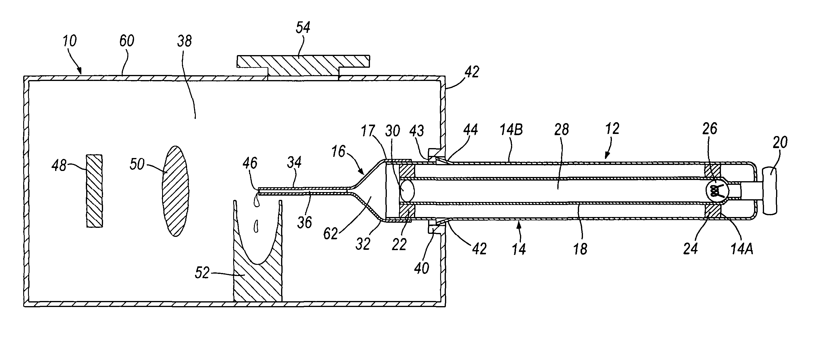
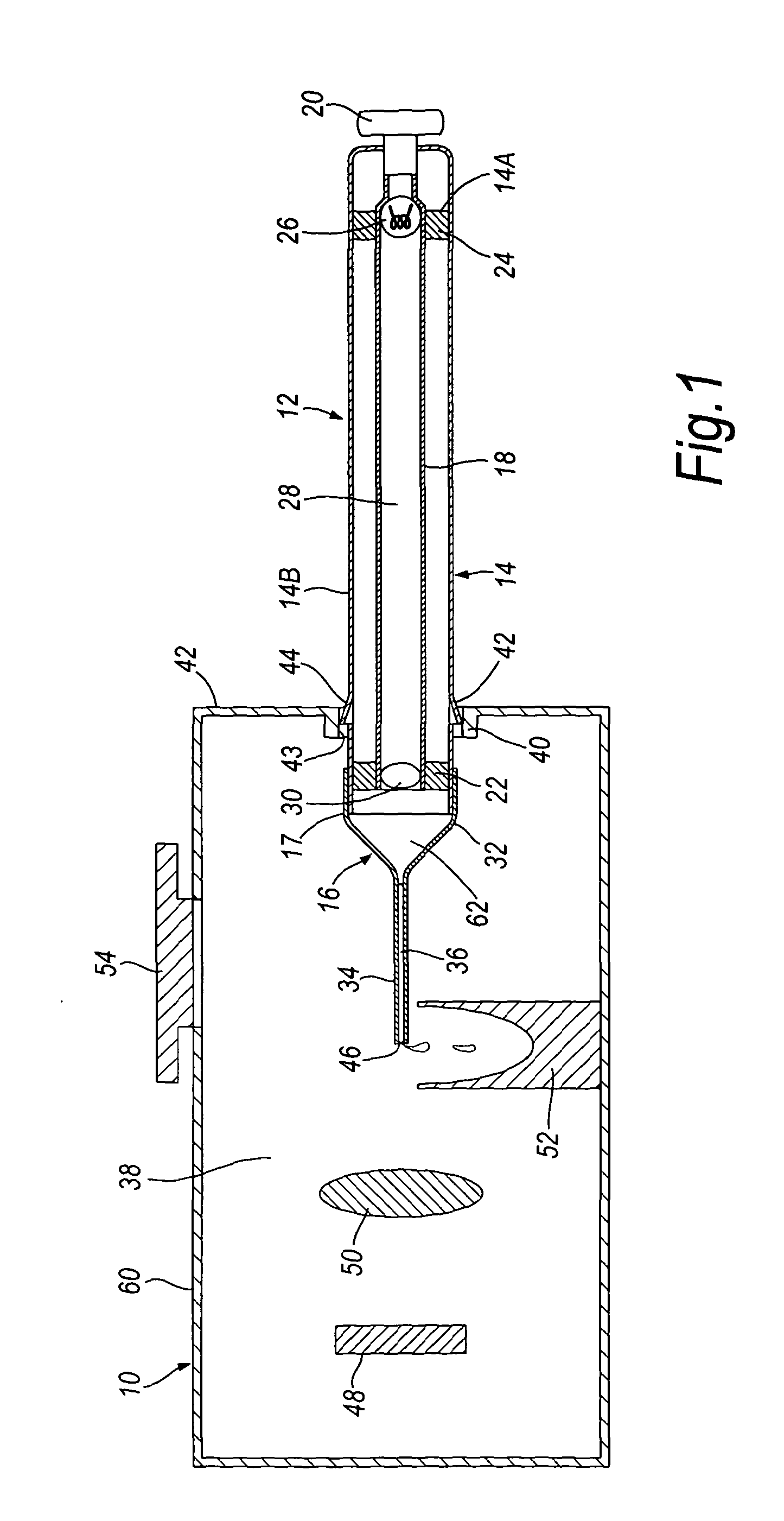
[0064]FIG. 1 illustrates an apparatus for light measurement comprising a light detector 48 within a housing 10. A pipette, generally shown as 12, is attached to the housing 10 and comprises a pipette body 14 and a pipette tip 16. The pipette tip 16 and the distal end portion of the pipette body 14 are positioned within the inner space 38 of the housing 10 in the measuring position. The pipette body 14 includes a plunger mechanism comprising a piston 18 and a plunger button 20. Attached to one end of the piston 18 is an annular ring 22 that abuts the inner wall of the pipette body 14 to locate the piston 18 centrally within the pipette body 14 and provide an air tight seal. At the other end of the piston 18 is provided a further annular ring 24 that is fixe...


PUM

PropertyMeasurementUnit
wavelengthaaaaaaaaaa
optical pathaaaaaaaaaa
lengthaaaaaaaaaa

Abstract

The present invention relates to a pipette (12) comprising a body portion (14) for aspirating a fluid sample (36) into a pipette tip (16) when attached thereto, wherein the body portion (14) comprises at least one light source (26), or an entry point for light from at least one light source, providing an optical path of light that passes through the sample (36) in a direction essentially along the longitudinal axis of the pipette tip (16). A method for measuring light output from a fluid sample (36), comprises providing a pipette tip (14) or capillary tube having first and second open ends (46, 68) with the sample (36) to be analysed contained therein, and detecting light output from an open end (46) of the pipette tip (16) or capillary tube. An apparatus and kit are also described. The pipette, apparatus, kit and method allow the accurate analysis and quantitative determination of minute amounts of biological samples.

Description

TECHNICAL FIELD[0001]The present invention relates to a pipette for use in spectrophotometrical analyses, and to an apparatus and a kit for the measurement of light absorbed by or emitted from a liquid sample. The present invention also relates to a method of using the pipette, apparatus and kit.BACKGROUND ART[0002]In recent years a great deal of technology has been developed to handle small volumes of liquid samples. Pipettes are liquid handling tools that are commonly used in molecular biology as well as in medical tests. Conventional pipettes generally include an elongated cylindrical body having at one end a coaxially mounted pipette tip, a cylindrical piston within a cavity of the pipette body, and an actuating mechanism for actuating the piston. The actuating mechanism may cause the piston to perform an upward stroke so that liquid is aspirated into the pipette tip or a downward stroke so that liquid is dispensed from the pipette tip.[0003]In a wide range of fields, samples ar...

Claims


Application Information

Patent Timeline
Patent Type & Authority Applications(United States)
IPC IPC(8): G01N21/59B01L3/02
CPCB01L3/021B01L2300/0654G01N2021/0346G01N21/03B01L2400/0478
Inventor PAGE, BRIAN
Owner PAGE BRIAN
Why Eureka
Try Eureka