Grating structure of 2d/3d switching display device

a display device and grating technology, applied in non-linear optics, instruments, optics, etc., can solve the problems of inability to apply patents in practical applications, inability to achieve reversible oxidation or reduction, and complex manufacturing process, so as to improve the efficiency and uniformity of the coloration of the solution type electrochromic material, improve the cladding property, and improve the effect of electric conductivity

Inactive Publication Date: 2012-09-06
J TOUCH CORPORATION
View PDF1 Cites 25 Cited by
  • Summary
  • Abstract
  • Description
  • Claims
  • Application Information

AI Technical Summary

Benefits of technology

[0018]When the present invention is used, the conductive wire layer disposed around the external side (or internal side) of one or two of the transparent conductive films and the conductive wire layer having a low resistance can accelerate the conduction speed of the current between the two transparent conductive films and discharge the electricity from the periphery towards the center uniformly, such that the efficiency and uniformity of the coloration of the solution type electrochromic material can be improved significantly. In addition, the present invention uses the first cladding layer of the conductive wire layer to increase the cladding property with the transparent conductive films, and the conductive layer can be attached onto the first cladding layer more easily. Finally, the second c...

Problems solved by technology

However, both patents of M368088 and M371902 have a common drawback of lacking a necessary electrolyte layer required by electrochromic devices, since ions are not supplied to the electrolyte layer 14 of the electrochromic layer 13, and the electrochromic layer 13 cannot produce the reversible oxidation or reduction to complete the coloration or decoloration successfully, so that the aforementioned patents are not feasible in practical applications.
In addition, the transparent conductive films 111, 121 and the electrochromic layer 13 are grid patterned when the grating structure 1 is used as a parallax barrier device, and whose manufacturing process requires a precise alignment for coating, spluttering or etching each laminated layer, such that a hollow a...

Method used


Image

  • Grating structure of 2d/3d switching display device
  • Grating structure of 2d/3d switching display device
  • Grating structure of 2d/3d switching display device

Examples


Embodiment Construction

[0028]To make it easier for our examiner to understand the technical contents of the present invention, preferred embodiments together with related drawings are used for the detailed description of the present invention as follows.

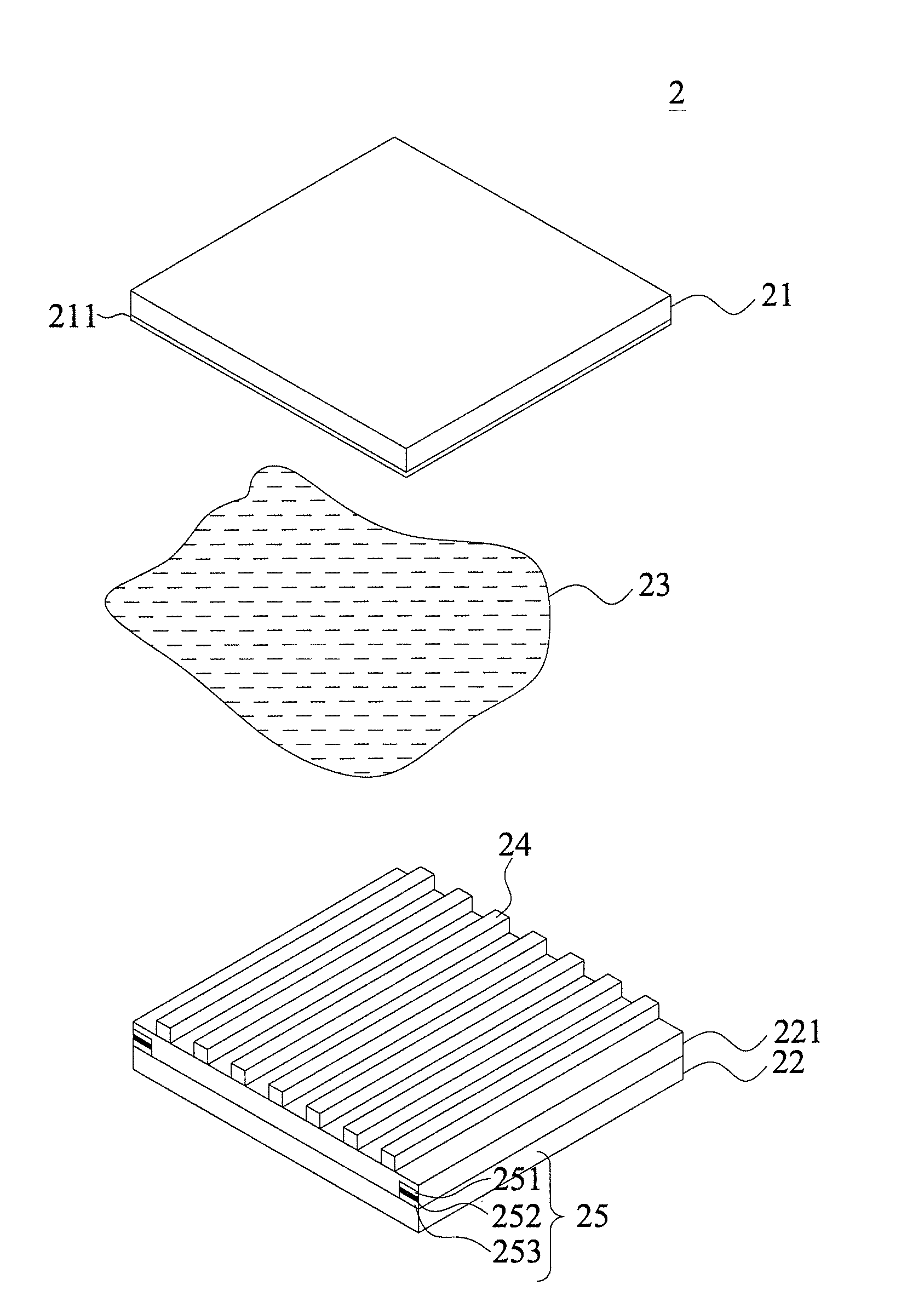
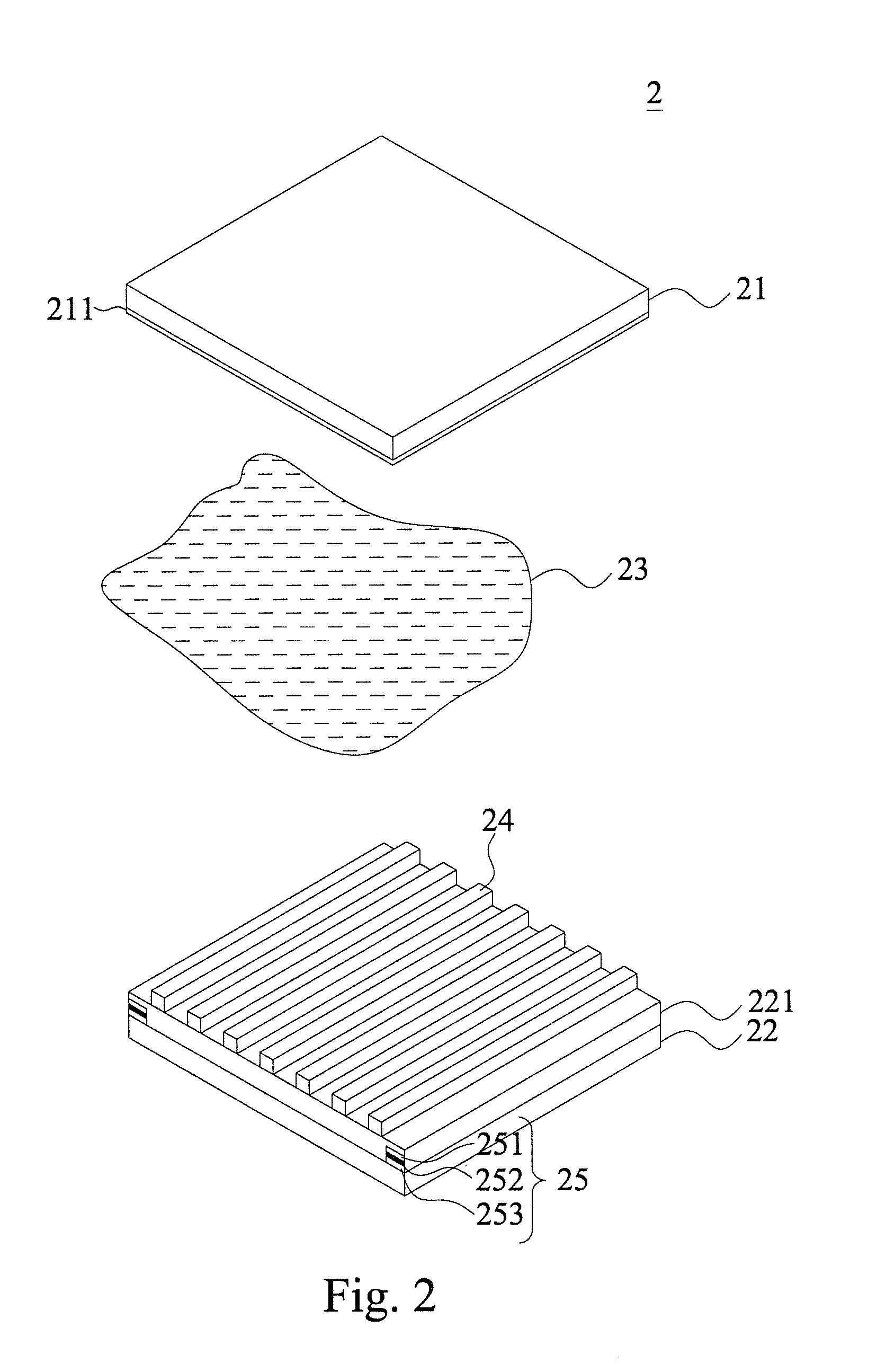
[0029]With reference to FIGS. 2 and 3 for an exploded view and a cross-sectional view of an assembly in accordance with a first preferred embodiment of the present invention respectively, a grating structure of a 2D / 3D switching display device 2 of the present invention comprises a first transparent substrate 21, a first transparent conductive film 211, a second transparent substrate 22, a second transparent conductive film 221, a solution type electrochromic material 23, an isolating element 24 and a conductive wire layer 25.

[0030]The first transparent conductive film 211 and the second transparent conductive film 221 are used together with the first transparent substrate 21 and the second transparent substrate 22, and the second transparent conductive fi...


PUM


Abstract

A grating structure of a 2D/3D switching display device comprises: a first transparent substrate, a first transparent conductive film; a second transparent substrate, and a second transparent conductive film disposed with an interval apart with each other on a side of the first transparent conductive film, such that a potential difference is produced between the first transparent conductive film and the second transparent conductive film; a solution type electrochromic material, disposed between the two transparent conductive films; an isolating element, made of an inorganic material, and disposed on a side of the second transparent conductive film; and a conductive wire layer, disposed on a lateral periphery of the first transparent conductive film and/or the second transparent conductive film. After the conductive wire layer is electrically conducted, the conductive wire layer with a low resistance accelerates the conduction of current, so as to improve the efficiency and uniformity of coloration.

Description

CROSS-REFERENCE TO RELATED APPLICATIONS[0001]This non-provisional application claims priority under 35 U.S.C. §119(a) on Patent Application No(s). 100107339 filed in Taiwan, R.O.C. on Mar. 4, 2011, the entire contents of which are hereby incorporated by reference.BACKGROUND OF THE INVENTION[0002]2. Field of the Invention[0003]The present invention relates to the field of display devices, and more particularly to a grating structure of a 2D / 3D switching display device having a frame made of a metal conductive wire for accelerating the conduction speed of current of a transparent conductive film to enhance the efficiency and uniformity of coloration.[0004]3. Description of the Prior Art[0005]In general, the principle of 3D image display technology adopts binocular disparity, such that a viewer's left and right eyes can receive different images respectively, and finally the viewer's brain merges the images into a 3D image. As to the naked-eye 3D display technology, the structure of the...

Claims


Application Information

Patent Timeline
IPC IPC(8): G02F1/15G02F1/1503
CPCG02F1/1521G02F1/1533G02F2201/44G02F2001/1536G02F1/155G02F1/1503
Inventor YEH, YU-CHOUWANG, CHAO-YILO, WEN-CHIHSUNG, CHI-HSIENYEH, TSUNG-HER
Owner J TOUCH CORPORATION
Why Eureka
Try Eureka