Thermal cycler

a cycler and cycle technology, applied in fluid controllers, laboratory glassware, chemistry apparatus and processes, etc., can solve the problems of large amount of reagents and long reaction time, and achieve the effect of reducing the siz

Inactive Publication Date: 2012-09-06
SEIKO EPSON CORP
View PDF7 Cites 10 Cited by
  • Summary
  • Abstract
  • Description
  • Claims
  • Application Information

AI Technical Summary

Benefits of technology

[0010]An advantage of some aspects of the invention is to provide a thermal cycler suitable for reduction in size.

Problems solved by technology

However, in the method of the related art, there are problems in that a large amount of reagent and a complicated apparatus are required to realize a thermal cycle required for reaction, or it takes a long time to react.

Method used


Image

  • Thermal cycler
  • Thermal cycler
  • Thermal cycler

Examples


first embodiment

1. Entire Configuration of a Thermal Cycler

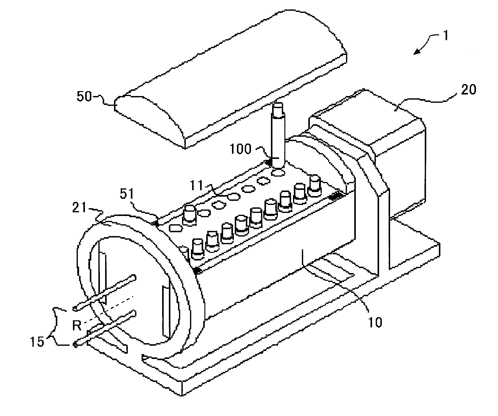
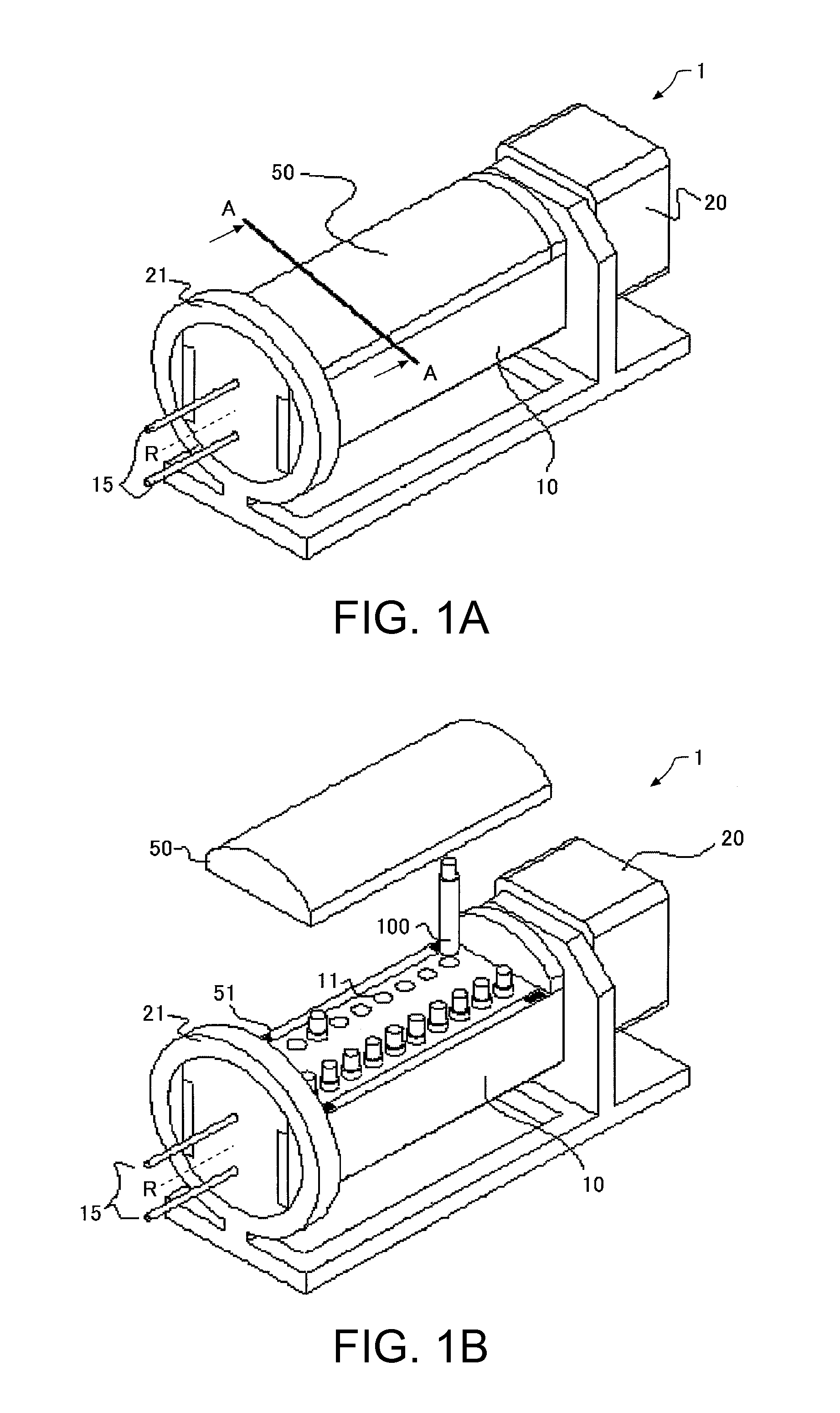
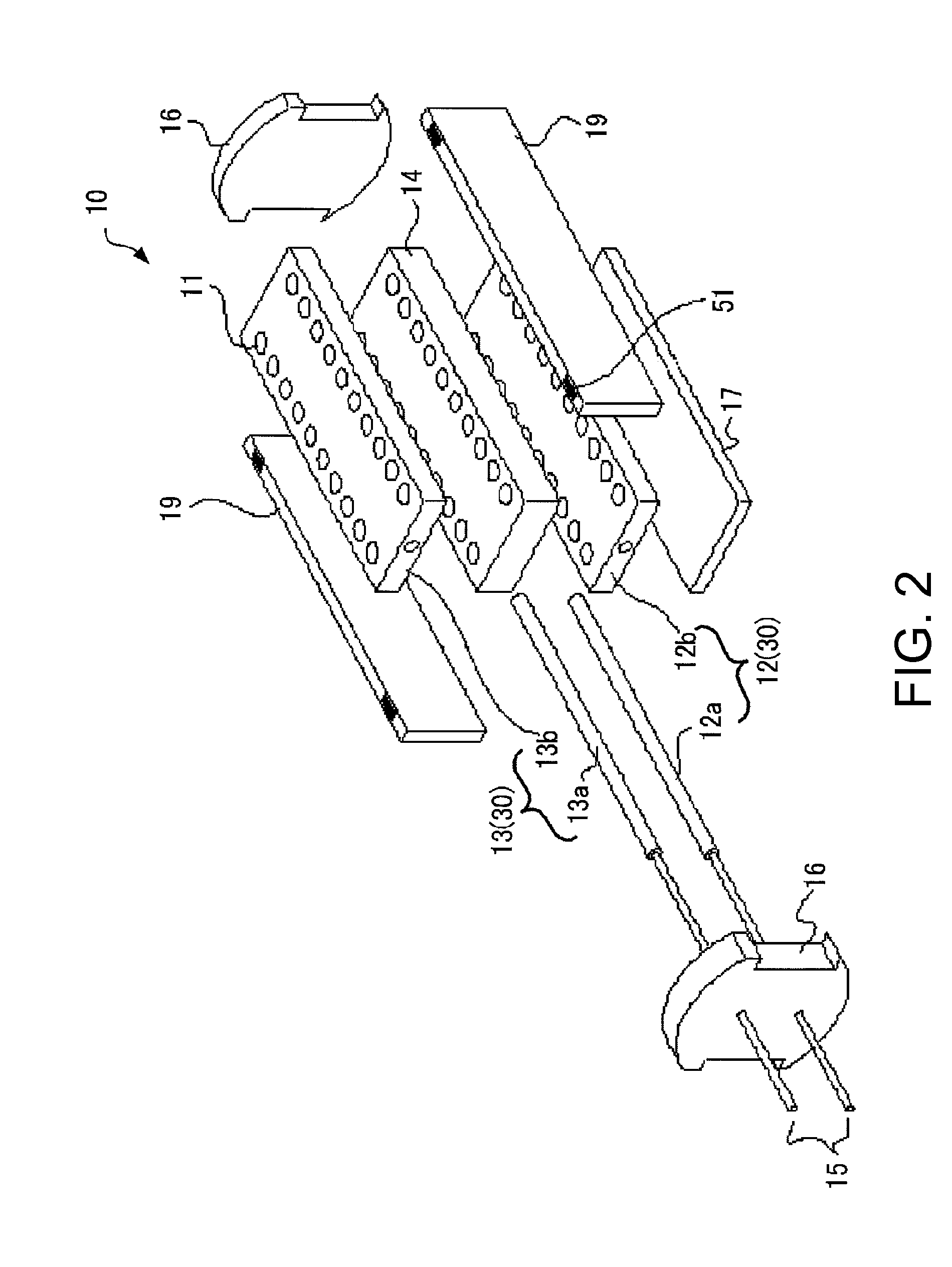
[0040]FIG. 1A is a perspective view showing a state in which a lid 50 of a thermal cycler 1 according to a first embodiment is closed, and FIG. 1B is a perspective view showing a state in which the lid 50 of the thermal cycler 1 according to the first embodiment is opened. FIG. 2 is an exploded perspective view of a main unit 10 of the thermal cycler 1 according to the first embodiment. FIG. 3 is a cross-sectional view diagrammatically showing a section taken along a plane passing through a line A-A and perpendicular to an axis of rotation R in FIG. 1A. In FIG. 3, an arrow g shows a direction in which the gravitational force acts.

[0041]The thermal cycler 1 according to the first embodiment includes holders 11 each configured to mount a reaction chamber 100 (described in detail later in section “3. Configuration of a reaction chamber to be loaded in a thermal cycler according to the first embodiment”) filled with reaction mixture 140 and liq...

second embodiment

5. Configurations of Thermal Cycler and Reaction Chamber to be Loaded Therein

[0118]FIG. 7A is a perspective view showing a state in which a lid 50 of a thermal cycler 2 according to a second embodiment is closed, and FIG. 7B is a perspective view showing a state in which the lid 50 of the thermal cycler 2 according to the second embodiment is opened. FIG. 8 is a cross-sectional view diagrammatically showing a section taken along a plane passing through a line B-B and perpendicular to the axis of rotation R in FIG. 7A. FIG. 9 is a cross-sectional view showing a configuration of a reaction chamber 100a which is to be loaded in the thermal cycler 2 according to the second embodiment. In FIGS. 8 and 9, the arrows g show the directions in which the gravitational force acts. In the description below, a configuration different from the thermal cycler 1 according to the first embodiment will be described in detail, and the same configurations as the thermal cycler 1 according to the first e...


PUM


Abstract

A thermal cycler includes a holder receiving a reaction chamber including a channel filled with reaction mixture and an immiscible liquid having different specific gravities and allowing the reaction mixture to move along an opposed inner wall, a temperature gradient forming unit forming a temperature gradient in the movement direction of the reaction mixture relative to the channel during loading into the holder, and a driving unit rotating the holder and temperature gradient forming unit about a rotation axis having a component perpendicular to the gravitational direction and a component perpendicular to the movement direction of the reaction mixture, and a maximum distance from the rotation axis to a point in the channel is smaller than a maximum distance connecting two points in the channel when projected on a plane perpendicular to the rotation axis.

Description

CROSS-REFERENCE[0001]This application claims priority to Japanese Patent Application No. 2011-043598, filed Mar. 1, 2011, the entirety of which is hereby incorporated by reference.BACKGROUND[0002]1. Technical Field[0003]The present invention relates to a thermal cycler.[0004]2. Related Art[0005]In recent years, as a result of genetic application technology development, medical treatment utilizing genes such as genetic diagnosis or genetic therapy are drawing attention and, in addition, many methods utilizing genes in determining breed varieties or breed improvement have been developed in agricultural and livestock industries. Technologies such as the PCR (Polymerase Chain Reaction) method are in widespread use utilizing genes. Nowadays, the PCR method is an absolutely imperative technology in the breakthrough of information on biological materials.[0006]The PCR method is a method of amplifying a target nucleic acid by applying a thermal cycle to a solution (reaction mixture) contain...

Claims


Application Information

Patent Timeline
Patent Type & Authority Applications(United States)
IPC IPC(8): B01L9/00
CPCB01L3/5082B01L7/525B01L7/54B01L2200/0673B01L2400/0457B01L2300/1822B01L2300/1827B01L2300/1838B01L2300/1811B01L9/06
Inventor KOEDA, HIROSHI
Owner SEIKO EPSON CORP
Why Eureka
Try Eureka