
Tumor Tracking System and Method for Radiotherapy

a tracking system and radiotherapy technology, applied in the field of radiotherapy, can solve the problems of unsatisfactory placement of internal imaging markers near the organs of patients, requiring training and practice days before treatment, etc., and achieves the effects of reducing treatment time, reducing the risk of potential harm, and reducing unnecessary harm to the health of patients

Inactive Publication Date: 2012-09-06
MITSUBISHI ELECTRIC RES LAB INC
View PDF8 Cites 50 Cited by
  • Summary
  • Abstract
  • Description
  • Claims
  • Application Information

AI Technical Summary

Benefits of technology

[0009]It is further object of the invention to minimize tumor position uncertainty during the treatment.
[0011]It is further object of the invention to minimize exposure of the patient to the unhealthy medical imaging, e.g., x-rays, during the treatment.
[0015]Embodiments of the invention are based on another realization that the certain correspondences between the motion of the surface of the skin and the tumor can be determined during treatment planning sessions, and be reused multiple times during the treatment delivery sessions, thus reducing the time of treatment, and the unnecessary harm to the health of the patient.
[0016]Moreover, those correspondences can be updated during the treatment preparation sessions with images having lower quality than the images required to determine the correspondence. Thus, the treatment time and the risk of potential harm are reduced without compromising the quality of the correspondence.

Problems solved by technology

One challenge during the delivery of radiation to a patient for treating a pathological anatomy, such as a tumor or a lesion, is identifying a location of the tumor.
Such training requires can require days of practice before treatment can begin.
Because exposing the patient continuously to x-rays to monitor the position of fiducial markers is undesirable, the position of the external markers are used to predict the position of the fiducial markers between longer periods of x-raying.
However, placement of the internal imaging markers near the organs of the patient is undesirable for number of medical and health related reasons.

Method used


Image

  • Tumor Tracking System and Method for Radiotherapy
  • Tumor Tracking System and Method for Radiotherapy
  • Tumor Tracking System and Method for Radiotherapy

Examples


Embodiment Construction

[0039]The radiotherapy treatment procedure typically includes multiple sessions such as a treatment planning session, a treatment preparation session and a treatment delivery session. Each session includes one or more procedures depending on a particular medical condition of a patient.

[0040]Treatment Planning Session

[0041]During the treatment planning session, data of the patient are acquired and an appropriate beam radiotherapy treatment procedure is planned including, but not limited to determination of the patient treatment position, identification of the target volumes and organs at risk, determination and verification of the treatment field geometry, and generation of simulation radiographs for each treatment beam.

[0042]The entire process of treatment planning involves many steps and usually involves a radiation oncology team, including an oncology physician, a clinical physicist, and a dosimetrist. The team is responsible for the overall integrity of the system to accurately a...


PUM


Abstract

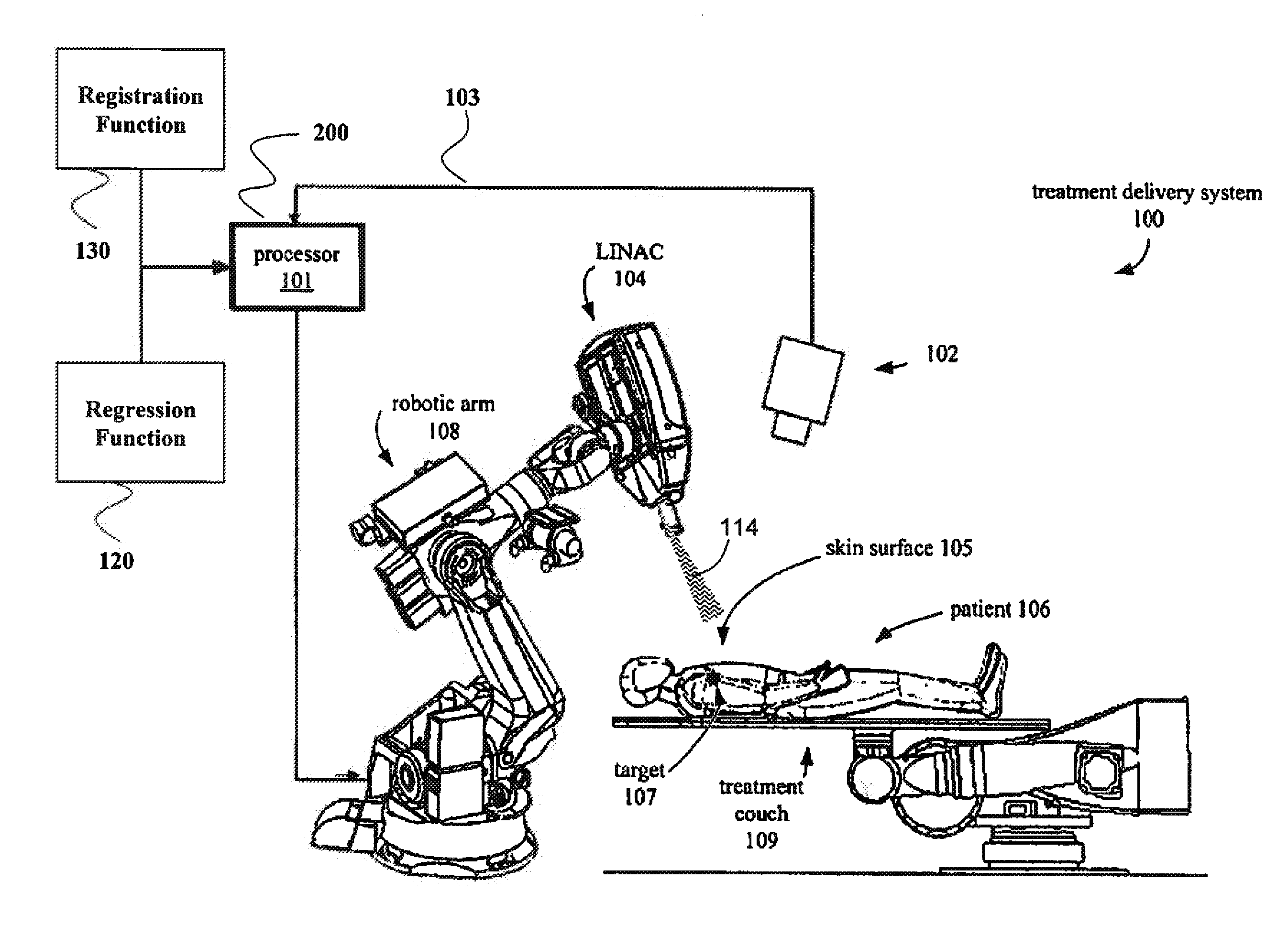
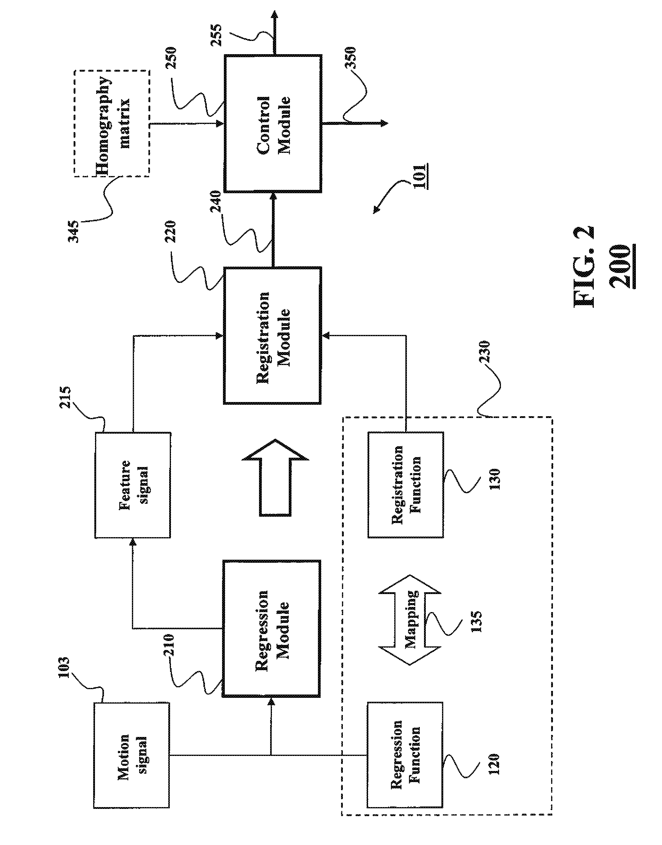
A system and method for tracking a tumor includes a regression module for selecting, using a motion signal and a regression function, a feature signal from a set of feature signals, each feature signal in the set of feature signals represents a medical image of the body of the patient, wherein the motion signal represents a motion of a surface of a skin of the patient caused by the respiration, and wherein the regression function is trained based on a set of observations of the motion signal synchronized with the set of feature signals; and a registration module for determining the location of the target object using the feature signal and a registration function, wherein the registration function registers each feature signal to a breath-hold location of the target object identified.

Description

FIELD OF THE INVENTION[0001]This invention relates generally to radiotherapy, and more particularly to tracking a motion of a pathological anatomy during respiration of a patient while delivering particle beam radiotherapy.BACKGROUND OF THE INVENTION[0002]One challenge during the delivery of radiation to a patient for treating a pathological anatomy, such as a tumor or a lesion, is identifying a location of the tumor. The most common localization methods use an x-ray to image the body of the patient to detect the location of the tumor. Those methods assume that the patient is stationary. However, even if the patient is stationary, radiotherapy requires additional methods to account for the motion of the tumor due to respiration, in particular for treating a tumor located near the lungs of the patient, e.g., posterior to the sternum. Breath-holding and respiratory gating are two primary methods used to compensate for the motion of the tumor during the respiration, while the patient r...

Claims


Application Information

Patent Timeline
IPC IPC(8): A61B6/00
CPCA61B5/1114A61B5/1128A61B5/113A61B5/1135A61B5/4836A61B6/12A61B6/4458A61N5/1037A61N5/1067A61N5/1083A61N2005/1059A61N2005/1062A61N2005/1087A61B6/5288A61B5/0036A61N5/1049A61N5/1068A61N2005/1058A61N2005/1061A61N2005/1074
Inventor PORIKLI, FATIH M.
Owner MITSUBISHI ELECTRIC RES LAB INC
Learn More