Stent grafts

Active Publication Date: 2012-09-06
TERUMO KK
View PDF2 Cites 16 Cited by
  • Summary
  • Abstract
  • Description
  • Claims
  • Application Information

AI Technical Summary

Benefits of technology

[0024]The stent graft fabric according to the present invention has superior endoleakage prevention due to being resistant to the occurrence of creasing, and has superior graft migration prevention due to promoting the infiltration of cells into gaps among microfibers in a dispersed state and integrating with the cells at the landing zone of the stent graft.

Problems solved by technology

However, stent graft surgery still has numerous problems.
An example thereof, although the portion where the stent graft fabric is to be contacted with a vessel wall and fixed thereto is referred to as the landing zone, problems may occur at this landing zone such as leakage of blood (hereinafter to be simply referred to as “endoleakage”) or migration of the stent graft from the landing zone due to inadequate fixation of the stent graft fabric (hereinafter to be simply referred to as “migration”).
This has been indicated to be caused by oversizing or looseness of the fabric at the landing zone where closest contact is to be made with the blood vessel.
As a result, as is described in Patent Documents 1 and 2 indicated below, the fabric may become loose after being expanded within the blood vessel and may end up sticking up inside the blood vessel in the manner of a sail, thereby enabling blood to be guided to the inside of the sail and resulting in the occurrence of endoleakage.
Although stent grafts are pushed into a blood vessel from the sheath and pushed apart with the expandable member, the status of the fabric following fixation in the landing zone cannot be confirmed by X-ray.
However, in the case of a diseased vessel wall, inner diameter gradually increases, and pressure applied to the vessel wall at the point that inner diameter has exceeded the inner diameter of the stent graft, namely, the strength that enables fixation of the stent graft, is lost.
Therefore, although a fixation method has been employed by which narrow hooks attached to the expandable member are driven into the vessel wall, this is unable to completely prevent migration.
As has been described above, the prior art has not yet solved the problems of endoleakage and migration.

Method used


Image

  • Stent grafts
  • Stent grafts
  • Stent grafts

Examples


example 1

[0087]Water jet treatment at a hydraulic pressure of 70 atm was carried out on the fabric A-1 produced in Comparative Example 1. The resulting fabric was designated as fabric A-2. The water permeability of the fabric A-2 as measured in accordance with ANSI / AAMI standards was 378 ml, burst strength as measured in accordance with ANSI / AAMI standards (burst test) was 16.8 kg, tear strength as measured in accordance ANSI / AAMI standards (suture retention test) was 0.82 kg, and thickness was 72 μm. Observation of the fabric with a scanning electron microscope (SEM) revealed that the microfibers were separated. Although gaps between fiber filaments varied at about 30 μm to 100 μm, the fiber filaments were adequately dispersed. When the fabric was embedded in resin to prepare sections and cross-sections containing microfiber bundles were observed, the microfiber filaments were observed to be in a dispersed state and large gaps were observed between the fiber filaments. Porosity of the micro...

example 2

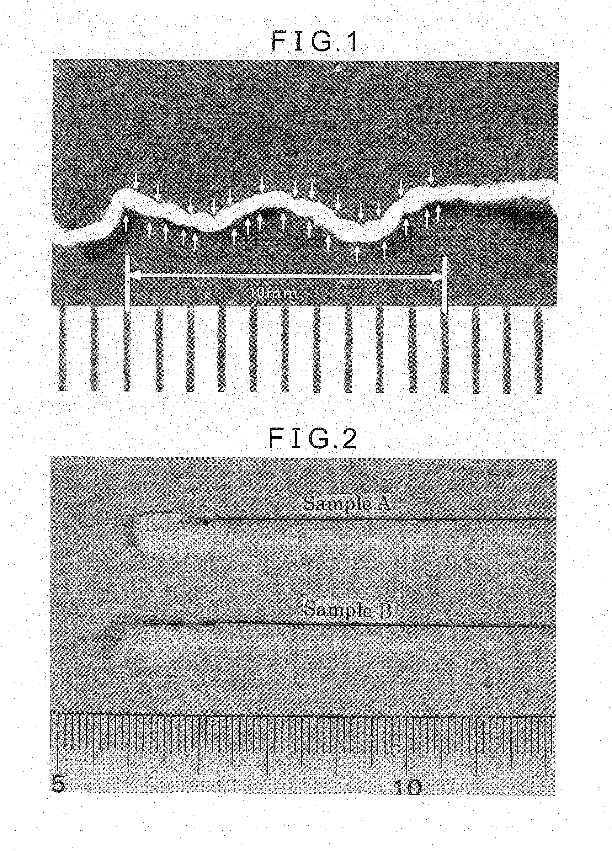
[0091]Microfiber bundles having a total linear density of 52 dtex / 350 filaments were selected, and false twist treatment was carried out at 4000 twists per meter. Optimum conditions during texturing, including thread tension, twisting speed, temperature and humidity, were selected empirically. False-twisted microfiber bundles were obtained with this procedure. Following false twist treatment, as a result of observing the fibers with a magnifying glass having a magnification of 10× without applying tension to the fibers and counting the number of crimps, fine crimps (microcrimps) were observed at the rate of about 25 per centimeter. These textured fibers are referred to as microcrimped microfiber bundles. FIG. 1 shows a photograph of a microcrimped microfiber bundle.

[0092]A plain woven tubular fabric having an inner diameter of 32 mm was produced by using regular fiber bundles having a total linear density of 34 dtex / 24 filaments for the warp and using microcrimped microfiber bundles...

example 3

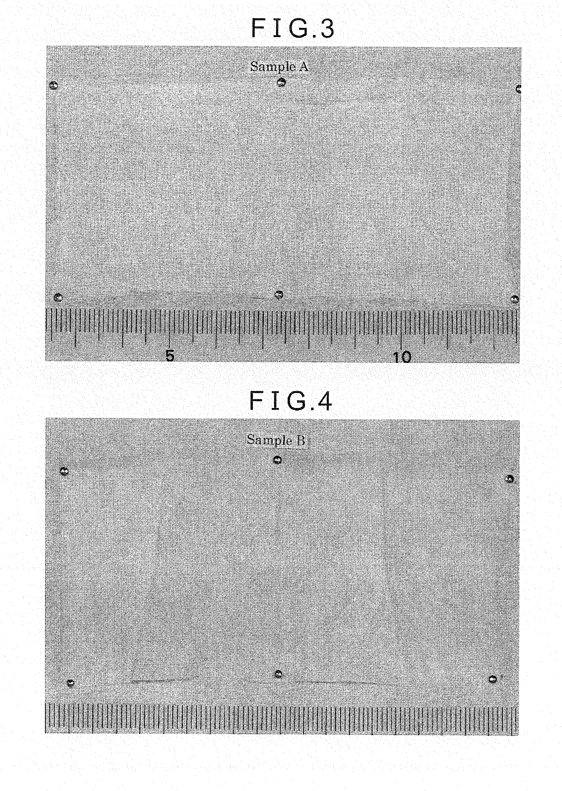
[0099]A 5 cm portion of the fabric A-2 having an inner diameter of 32 mm was removed and attempted to be inserted into a sheath. Although the fabric tightly fit into a 7 French (2.3 mm) sheath, it was easily able to be inserted into an 8 French (2.7 mm) sheath. In order to compare with the sheath-inserted fabric D-1 described in Comparative Example 9, the fabric A-2 was inserted into a 12 French sheath. This state was referred to as “sheath-inserted fabric A-2”.

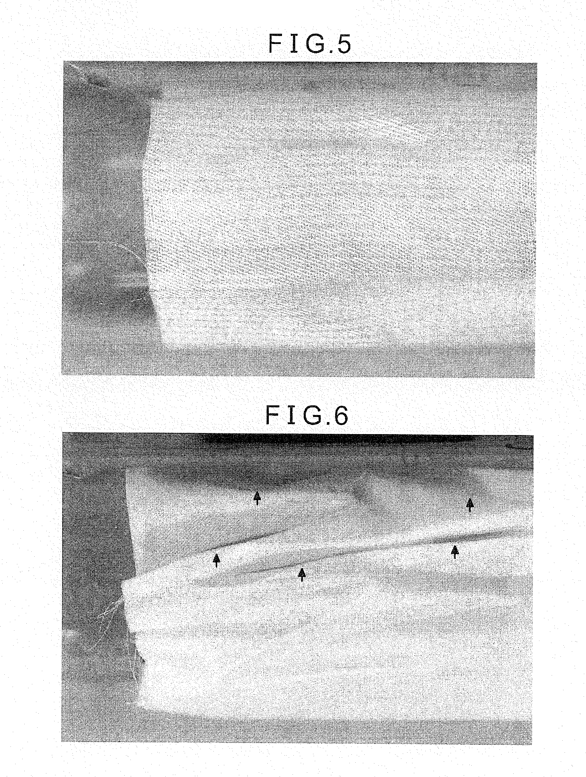
[0100]The aforementioned “sheath-inserted fabric A-2” and “sheath-inserted fabric D-1” are shown in FIG. 2. The sheath-inserted fabrics were subsequently sterilized by autoclaving for 20 minutes at 121° C., after which the fabrics were removed from the sheaths and spread out, the states at that time being respectively shown in FIGS. 3 and 4. Sample A indicates the “sheath-inserted fabric A-2”, while Sample B indicates the “sheath-inserted fabric D-1”. After autoclaving, although lines in the manner of shallow creases were abl...


PUM

PropertyMeasurementUnit
Lengthaaaaaaaaaa
Lengthaaaaaaaaaa
Thicknessaaaaaaaaaa

Abstract

Provided is a stent graft that has superior prevention of endoleakage due to being resistant to creasing, and has superior prevention of graft migration as a result of promoting cell infiltration into gaps among microfibers in a dispersed state and forming an integrated structure with the cells in the landing zone of the stent. The stent graft according to the present invention is a stent graft comprising a stent graft fabric that has microfiber bundles consisting essentially of microfilaments having a filament linear density of 0.5 dtex or less, and said microfiber bundles having a total linear density of 10 to 60 dtex / 120 to 3000 filaments, for the warp and / or weft, and in which the porosity of the microfiber bundles is 30% to 95%, wherein said stent graft has said stent graft fabric being located in at least 1 cm range from the central end.

Description

TECHNICAL FIELD[0001]The present invention relates to a fabric for a stent graft (hereinafter to be simply referred to as the “fabric”) having superior endoleakage prevention due to resistance to the occurrence of creasing as well as superior graft migration prevention due to the use of microfibers having superior cytophilicity, and to a stent graft that uses the fabric.BACKGROUND ART[0002]Stent graft surgery is a procedure performed for treatment of an abdominal aortic aneurysm or thoracic aortic aneurysm and the like that consists of inserting a tubular fabric and an expandable member contained in a sheath into an exposed blood vessel by making a small incision in the femoral region, continuing to insert until the affected region is reached, and then extending the tubular stent graft fabric with the expandable member and positioning in the blood vessel so as to span normal portions in front of and in back of the affected region so as to repair the affected region from within the b...

Claims


Application Information

Patent Timeline
IPC IPC(8): A61F2/06
CPCA61F2/07D02G1/0206A61L31/146D10B2401/10D10B2509/06D03D15/0061D03D1/00D03D3/02D03D15/33A61F2/82A61F2/06A61F2/95A61L27/00
Inventor SHIROKAZE, JUNICHINOISHIKI, YASUHARU
Owner TERUMO KK
Why Eureka
Try Eureka