Optical observation instrument with at least two optical transmission channels that respectively have one partial ray path

a technology of optical transmission channel and optical observation instrument, which is applied in the field of optical observation instrument with, can solve the problems of large installation volume, large installation volume of greenough-type system, and relatively high cost of providing double the number of optical systems and image sensors, and achieves reduced installation length of camera adapters, improved image quality, and high resolution

Active Publication Date: 2012-09-13
CARL ZEISS MEDITEC AG
View PDF1 Cites 8 Cited by
  • Summary
  • Abstract
  • Description
  • Claims
  • Application Information

AI Technical Summary

Benefits of technology

[0029]The camera adapter optical system can be arranged entirely behind the deflection element. However, alternatively, the deflection element can also be part of the camera adapter optical system. In this case, the camera adapter optical system is embodied such that one or more lenses are situated between the deflection element and the tilting mirror matrix, whereas the remaining elements are situated between the image sensor and the deflection element. This can reduce the installation length of the camera adapter. The camera adapter optical system can more particularly be embodied as a zoom system. In this case, it is particularly advantageous if the camera adapter optical system has a stationary entry pupil plane at the point of the deflection element.
[0030]For an image sensor, the optical observation instrument can have a color sensor, which is fed the partial ray bundle that was deflected by the tilting mirror matrix. However, alternatively, there may also be at least three monochrome image sensors and a color divider for dividing the partial ray bundle into at least three color channels, i.e. into at least three spectral ranges. Here the monochrome image sensors are arranged with respect to the color divider such that one color channel of the partial ray bundle is fed to each image sensor. Such structures are known as e.g. 3CCD cameras. Compared to systems with a common image sensor for all colors, they offer a higher resolution and better image quality. By way of example, a so-called Philips prism or a beamsplitter cube (X-cube) can be used as a color divider.

Problems solved by technology

Such arrangements have disadvantages as a result of the underlying principle, for example a large installation volume and relatively high costs for providing double the number of optical systems and image sensors.
Like in the case of telescope systems with a common main objective and further optical components separated into stereo channels, Greenough-type systems have a large installation volume and high costs for providing double the number of optical components.
Moreover, Greenough-type systems have complex mechanical designs.
However, it is disadvantageous that a mechanical shutter may cause vibrations and noise.
Furthermore, the inertial mass of the shutter component means that the switching frequency cannot be modified abruptly.
As a result, only a fraction of the theoretically possible integration time per frame on the image sensor can be used, which in turn leads to a loss in image brightness.
Thus, overall, rotating stops do not constitute a light-efficient solution for switching channels between a plurality of pupil pairs that are rotated with respect to one another.
However, a disadvantage of liquid-crystal stops is that, as a result of the underlying principle, they are only able to transmit a fraction of the light flow over the stereo channel in the allow-passage setting.
Since, as a result of the underlying principle, liquid-crystal shutters can only switch light of one polarization state but most applications use unpolarized light sources, there typically are light losses of at least 50%.
However, the actual light losses generally are even greater since the liquid-crystal medium itself only has a restricted transmission of typically 70 to 80%
Thus, the use of liquid-crystal displays on polymer basis does not render possible a high-contrast separation of the stereo channels.

Method used


Image

  • Optical observation instrument with at least two optical transmission channels that respectively have one partial ray path
  • Optical observation instrument with at least two optical transmission channels that respectively have one partial ray path
  • Optical observation instrument with at least two optical transmission channels that respectively have one partial ray path

Examples


Embodiment Construction

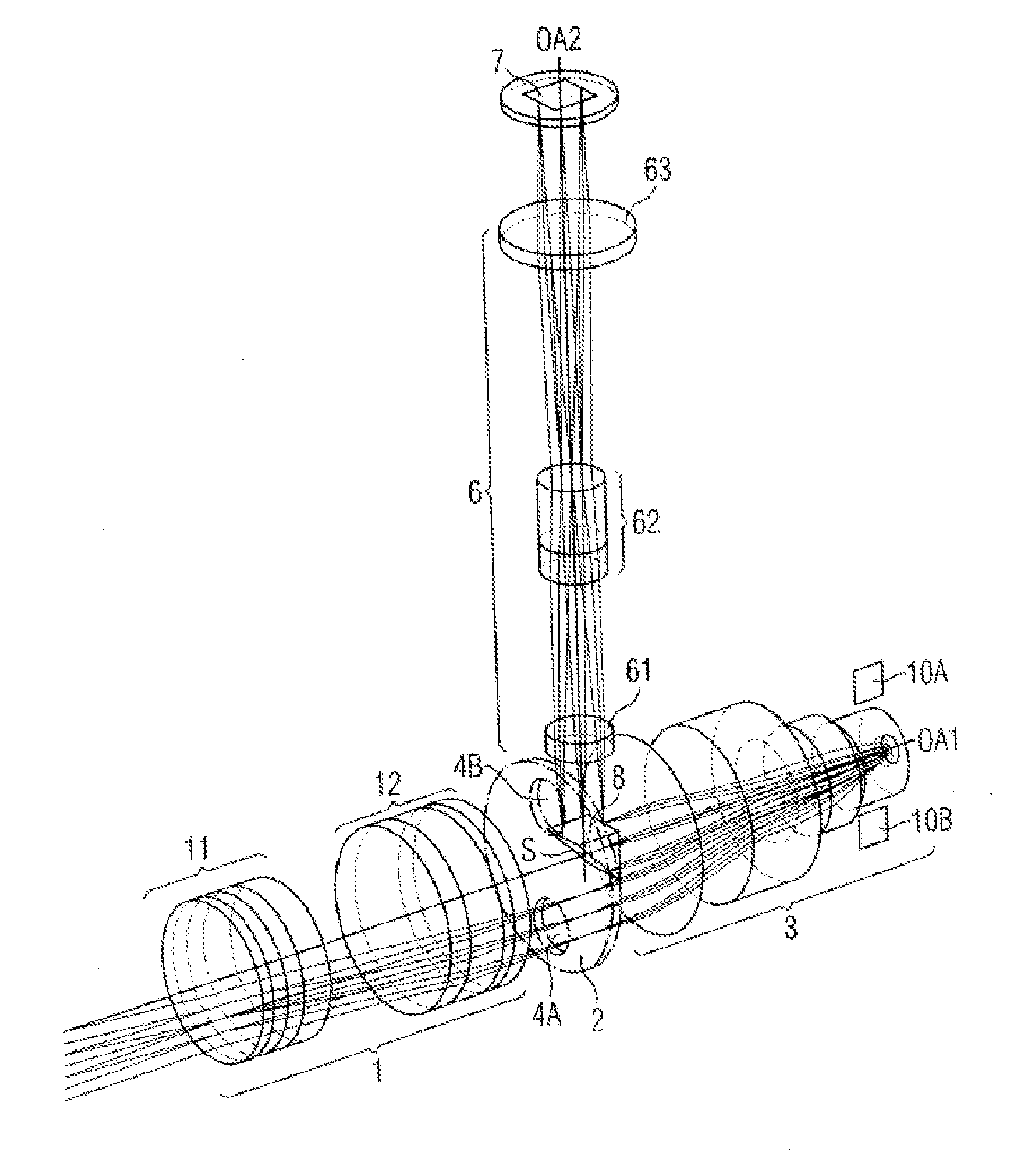
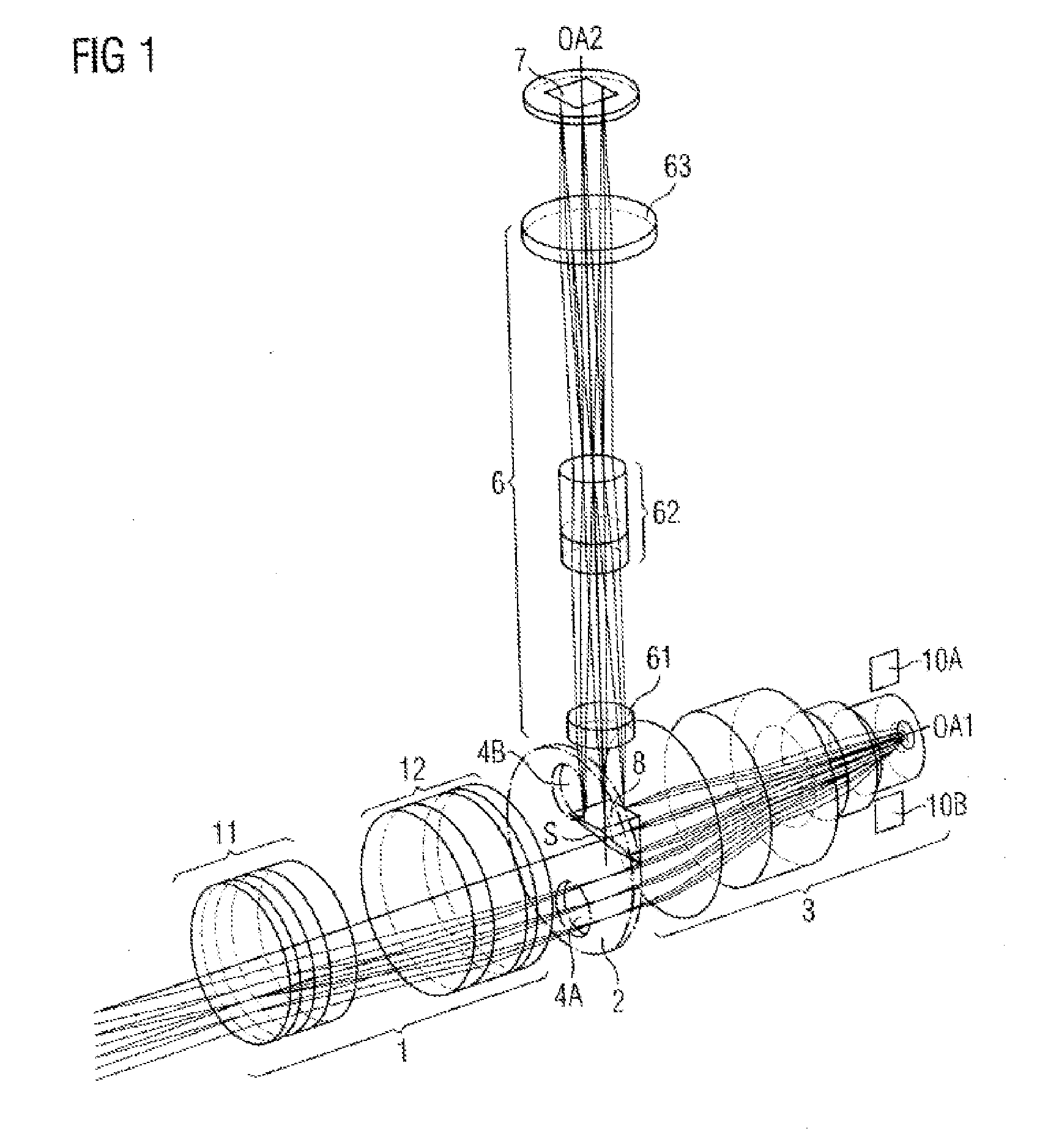
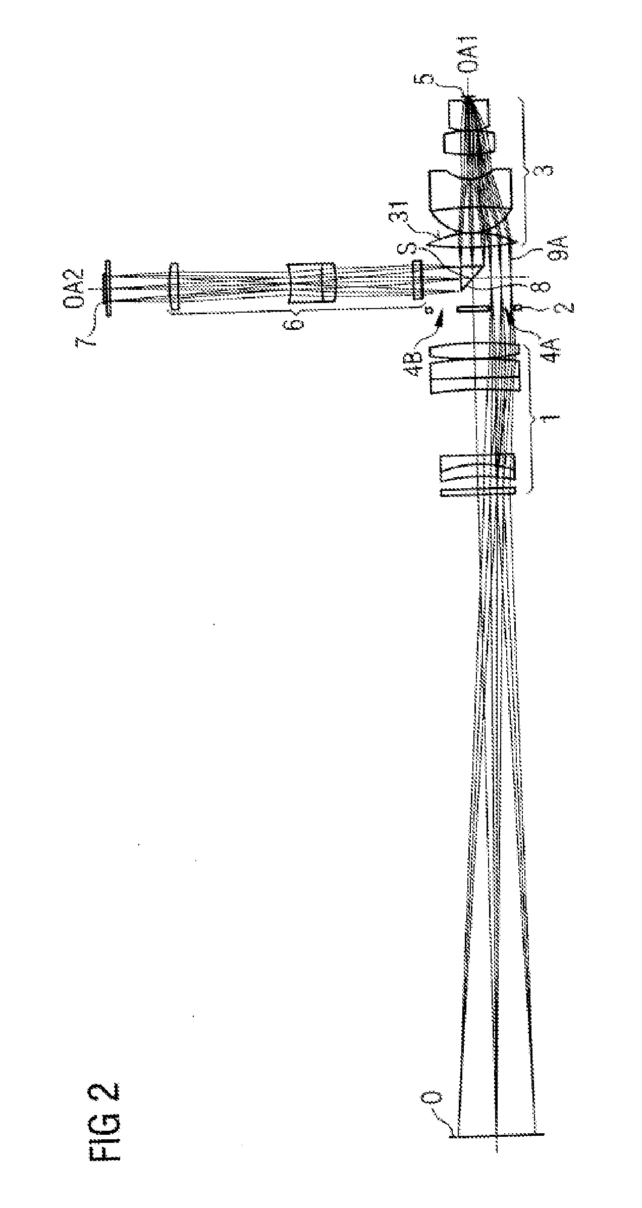
[0040]In the following text and with reference to FIGS. 1 to 4, a digital surgical microscope is described as an exemplary embodiment for an optical observation instrument according to the invention. The figures merely illustrate the optical components of the surgical microscope and (in FIGS. 2 and 3) the partial ray paths in order to avoid unnecessary complication of the figures. Here, FIG. 1 shows a perspective representation of the components. FIGS. 2 and 3 show the stereoscopic partial ray paths in a sectional view.

[0041]The surgical microscope embodied according to the invention comprises a main objective 1, an aperture stop 2, an intermediate imaging optical system 3 and a tilting mirror matrix 5, which are arranged one behind the other along a first optical axis section OA1 from the object side to the observer side. The surgical microscope furthermore comprises a camera adapter optical system 6 and an electronic image sensor 7, which are arranged one behind the other along a ...


PUM


Abstract

An optical observation instrument has two optical transmission channels for transmitting two partial ray bundles (9A, 9B). The optical observation instrument has a main objective (1) common to the optical transmission channels, an electronic image sensor (7) for sequentially recording the partial ray bundles (9A, 9B), an intermediate imaging optical system (3) between the main objective (1) and the image sensor (7) and common to the optical transmission channels, and a tilting mirror matrix (5) between the main objective (1) and the image sensor (7). The intermediate imaging optical system (3) is arranged so that the respective partial ray bundle (9A, 9B) is deflected toward the image sensor (7) and passes the intermediate imaging optical system (3) both on the way from the main objective (1) to the tilting mirror matrix (5) and on the way from the tilting mirror matrix (5) to the image sensor (7).

Description

BACKGROUND OF THE INVENTION[0001]1. Field of the Invention[0002]The present invention relates to an optical observation instrument with at least two optical transmission channels that respectively have one partial ray path and an electronic image recording system for recording, sequentially in time, the partial ray bundles transmitted by the optical transmission channels. An example of such an optical observation instrument is a stereoscopic optical observation instrument such as e.g. a stereo microscope, more particularly a surgical microscope. In such an instrument, the stereo channels are the optical transmission channels, each of which transmitting a stereoscopic partial ray path, i.e. the ray path for a stereoscopic partial image, to the electronic image sensor.[0003]2. Description of the Related Art[0004]The prior art has disclosed a number of arrangements for recording stereoscopic images, in which separate image receivers and, at least in part of the imaging ray path, separa...

Claims


Application Information

Patent Timeline
Patent Type & Authority Applications(United States)
IPC IPC(8): H04N13/02H04N15/00
CPCG02B21/22G02B26/0833G02B21/0012
Inventor PRETORIUS, MARCOGEISSLER, ENRICORUDOLPH, GUENTERNIETEN, CHRISTOPHMOFFAT, BRYCE ANTONHOEGELE, ARTUR
Owner CARL ZEISS MEDITEC AG
Why Eureka
Try Eureka