Stent fabrication via tubular casting processes

a tubular casting and fabrication process technology, applied in the field of manufacturing processes for forming or creating devices, can solve the problems of reducing the mechanical properties of the formed substrate, reducing flexibility, and generally a transition from brittle to ductile failur

Active Publication Date: 2012-09-13
RAZMODICS LLC
View PDF8 Cites 20 Cited by
  • Summary
  • Abstract
  • Description
  • Claims
  • Application Information

AI Technical Summary

Benefits of technology

[0008]An example of such a casting process is to utilize a dip-coating process. The utilization of dip-coating to create a polymeric substrate having such desirable characteristics results in substrates which are able to retain the inherent properties of the starting materials. This in turn results in substrates having a relatively high radial strength which is retained through any additional manufacturing processes for implantation. Additionally, dip-coating the polymeric substrate also allows for the creation of substrates having multiple layers.
[0011]Parameters such as the number of times the mandrel is immersed, the sequence and direction of dipping, the duration of time of each immersion within the solution, as well as the delay time between each immersion or the drying or curing time between dips and dipping and / or withdrawal rates of the mandrel to and / or from the solution may each be controlled to result in the desired mechanical characteristics. Formation via the dip-coating process may result in a polymeric substrate having half the wall thickness while retaining an increased level of strength in the substrate as compared to an extruded polymeric structure.
[0013]Dip-coating can be used to impart an orientation between layers (e.g., linear orientation by dipping; radial orientation by spinning the mandrel; etc.) to further enhance the mechanical properties of the formed substrate. As radial strength is a desirable attribute of stent design, post-processing of the formed substrate may be accomplished to impart such attributes. Typically, polymeric stents suffer from having relatively thick walls to compensate for the lack of radial strength, and this in turn reduces flexibility, impedes navigation, and reduces arterial luminal area immediately post implantation. Post-processing may also help to prevent material creep and recoil (creep is a time-dependent permanent deformation that occurs to a specimen under stress, typically under elevated temperatures) which are problems typically associated with polymeric stents.
[0015]Yet another method may apply the expansion force by application of a pressurized inert gas such as nitrogen within the substrate lumen. A completed substrate may be placed inside a molding tube which has an inner diameter that is larger than the cast cylinder. A distal end or distal portion of the cast cylinder may be clamped or otherwise closed and a pressure source may be coupled to a proximal end of the cast cylinder. The entire assembly may be positioned over a nozzle which applies heat to either the length of the cast cylinder or to a portion of cast cylinder. The increase in diameter of the cast cylinder may thus realign the molecular orientation of the cast cylinder to increase its radial strength. After the diameter has been increased, the cast cylinder may be cooled.
[0016]Once the processing has been completed on the polymeric substrate, the substrate may be further formed or machined to create a variety of device. One example includes stents created from the cast cylinder by cutting along a length of the cylinder to create a rolled stent for delivery and deployment within the patient vasculature. Another example includes machining a number of portions to create a lattice or scaffold structure which facilitates the compression and expansion of the stent.

Problems solved by technology

With an increase in the molecular weight of a polymer, there is generally a transition from brittle to ductile failure.

Method used


Image

  • Stent fabrication via tubular casting processes
  • Stent fabrication via tubular casting processes
  • Stent fabrication via tubular casting processes

Examples


Embodiment Construction

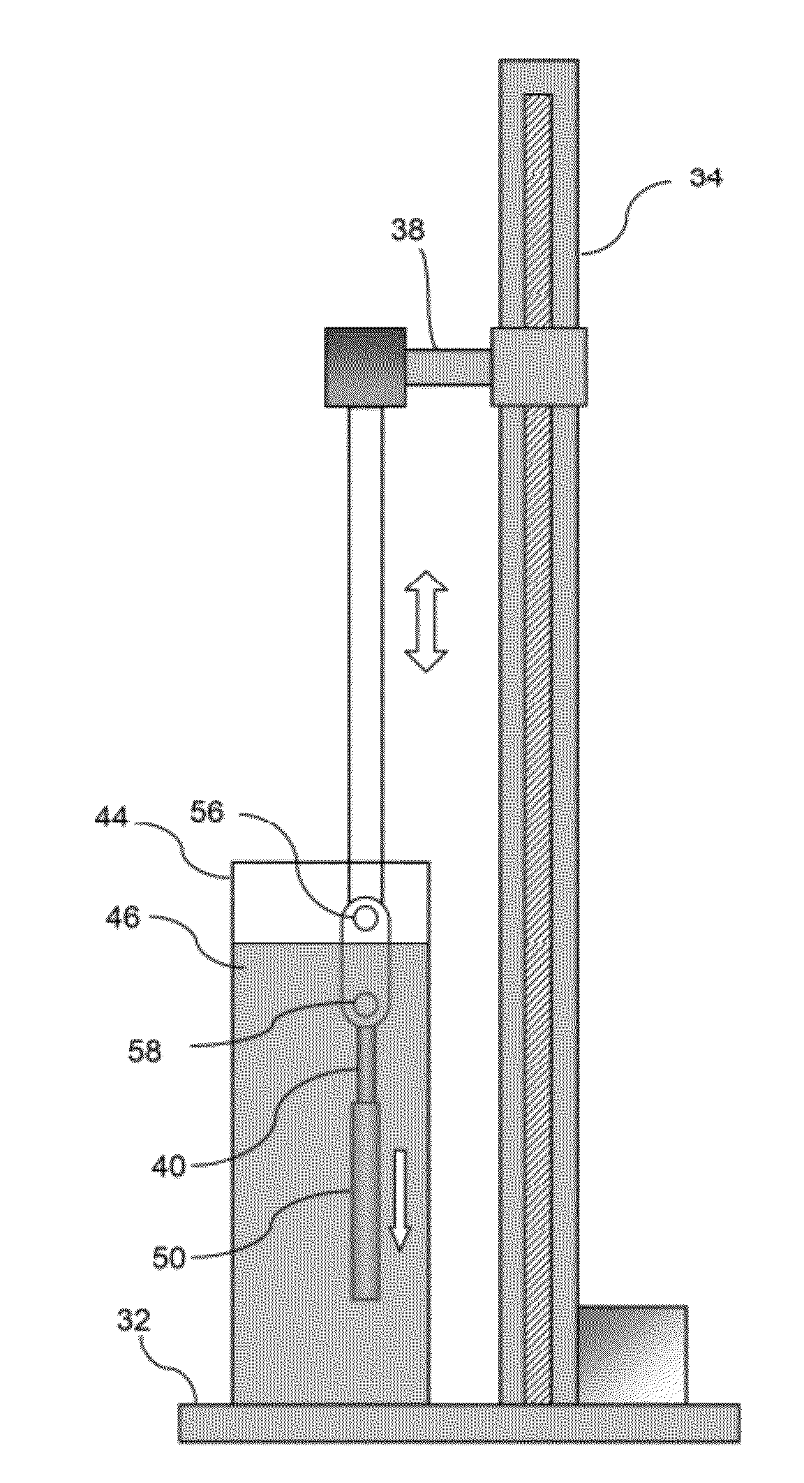
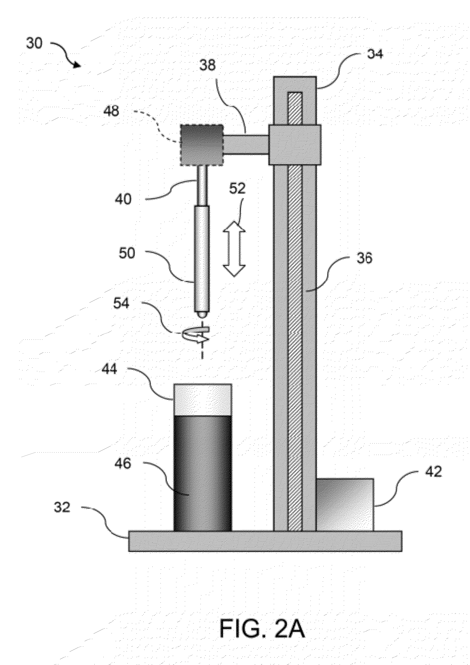
[0032]In manufacturing implantable devices from polymeric materials such as biocompatible and / or biodegradable polymers, a number of casting processes described herein may be utilized to develop substrates, e.g., cylindrically shaped substrates, having a relatively high level of geometric precision and mechanical strength. These polymeric substrates can then be machined using any number of processes (e.g., high-speed laser sources, mechanical machining, etc.) to create devices such as stents having a variety of geometries for implantation within a patient, such as the peripheral or coronary vasculature, eta.

[0033]An example of such a casting process is to utilize a dip-coating process. The utilization of dip-coating to create a polymeric substrate having such desirable characteristics results in substrates which are able to retain the inherent properties of the starting materials. This in turn results in substrates having a relatively high radial strength which is mostly retained th...


PUM


Abstract

Tubular casting processes, such as dip-coating, may be used to form substrates from polymeric solutions which may be used to fabricate implantable devices such as stents. The polymeric substrates may have multiple layers which retain the inherent properties of their starting materials and which are sufficiently ductile to prevent brittle fracture. Parameters such as the number of times the mandrel is immersed, the duration of time of each immersion within the solution, as well as the delay time between each immersion or the drying or curing time between dips and withdrawal rates of the mandrel from the solution may each be controlled to result in the desired mechanical characteristics. Additional post-processing may also be utilized to further increase strength of the substrate or to alter its shape.

Description

CROSS-REFERENCE TO RELATED APPLICATIONS[0001]This application is a divisional of U.S. patent application Ser. No. 12 / 143,659 filed Jun. 20, 2008, the content of which is hereby incorporated by reference in its entirety.FIELD OF THE INVENTION[0002]The present invention relates generally to manufacturing processes for forming or creating devices which are implantable within a patient, such as medical devices. More particularly, the present invention relates to methods and processes for forming or creating tubular substrates which may be further processed to create medical devices having various geometries suitable for implantation within a patient.BACKGROUND OF THE INVENTION[0003]In recent years there has been growing interest in the use of artificial materials, particularly materials formed from polymers, for use in implantable devices that come into contact with bodily tissues or fluids particularly blood. Some examples of such devices are artificial heart valves, stents, and vascul...

Claims


Application Information

Patent Timeline
Patent Type & Authority Applications(United States)
IPC IPC(8): A61F2/82
CPCA61F2/24A61F2/82A61F2002/30062A61F2002/30535A61F2210/0004A61L31/148A61F2240/004A61L31/04A61L31/14B29C49/00A61F2/07A61F2210/0019A61L31/06A61L31/16B29C41/003B29C41/14B29K2105/0035B29K2995/0056B29L2031/7532
Inventor RAMZIPOOR, KAMALCHIA, ALFRED N. K.WANG, LIWEI
Owner RAZMODICS LLC
Why Eureka
Try Eureka