
Sealed, slim-line constant force, generation unit

Inactive Publication Date: 2012-09-20
CARR CYNTHIA KRIESMER
View PDF14 Cites 6 Cited by
  • Summary
  • Abstract
  • Description
  • Claims
  • Application Information

AI Technical Summary

Benefits of technology

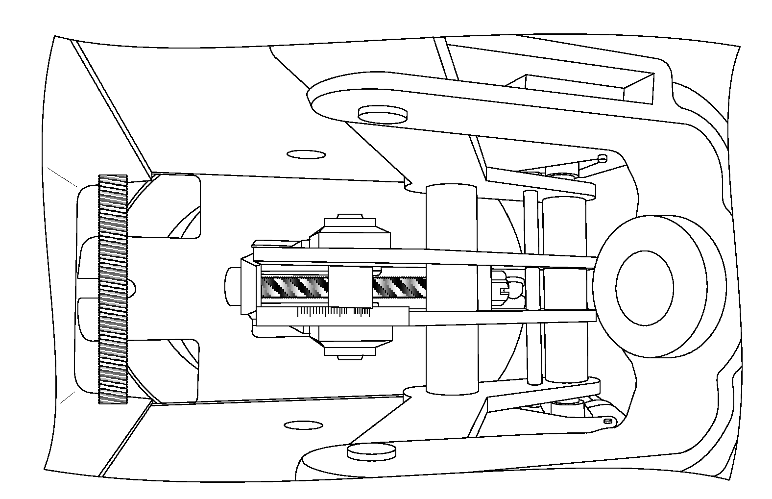
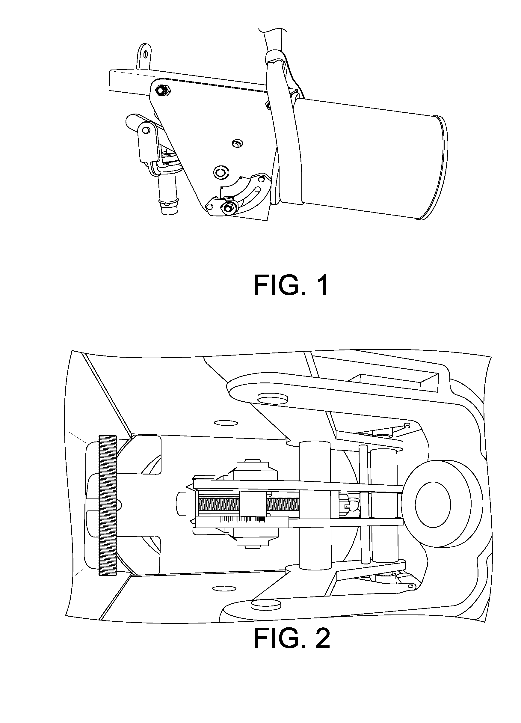
[0011]This disclosure provides a simplified single geometric configuration that can support a wide range of load ratings by providing a means for changing the output force of the system without a need to replace the entire system. To provide such a constant and dependable force, the disclosure operates using a sealed spring system with a specialized lever-arm system that outputs a constant force during lever-arm travel.
[0013]In the disclosure, the spring system may be detachable from the rest of the system. The puller rod, spring load rod, and the conical spring washers may be interchangeable and may be manipulated to best offset the load displacement. The preferred configuration of the disclosure uses Belleville washers and Belleville spacers as the spring system components. One or more Belleville washers may be combined to form a small and compact Belleville spring stack. This type of spring system, as compared with the use of large coiled spring systems, reduces the geometric size of the compact force generation system and may result in a substantial weight and size reduction over the prior art.
[0014]Unlike the prior art, this disclosure provides a technique to handle a large range of load ratings. By providing a screwed, interchangeable puller rod and interchangeable Belleville spring systems, the load rating of any unit may be changed in place without the need for special tools. The reduced weights of the spring system and puller rod enables changing of the load range change without lifting or using any additional lifting support equipment. The load range change may be accomplished in a matter of minutes due to design simplicity, and may improve maintenance safety due to the elimination of lifting support equipment use.
[0015]This disclosure also provides for a sealed system. The spring system components may be protected from external environmental conditions by a spring housing unit that houses the spring components and a seal system and o-ring that securely seals the ends of the spring system and attaches it to the puller rod. Environmentally exposed components, including the housing unit, may be constructed of stainless steel to control corrosion and extend the service life of the units. A sealed spring system with such corrosion resistant design may eliminate force generating system corrosion and fouling while further protecting all other components from corrosion. Even after a load range change, the unit's sealing system remains intact.
[0019]The benefits of the disclosure include an interchangeable single geometric configuration providing a reduction in inventory requirements and costs, support of in-place load rating modification and acceleration of product delivery. The components in the disclosure may be cut by a laser fabrication process and thereby also offering fabrication advantages. All components are like-designed and can be stored unassembled and unwelded as needed, thereby generating a significant reduction in storage space requirements. Also, with use of tab and slot interlocking mechanisms, rapid assembly and welding is assured due to the reduced requirement of alignment and layout for tolerancing.

Problems solved by technology

This type of spring system, as compared with the use of large coiled spring systems, reduces the geometric size of the compact force generation system and may result in a substantial weight and size reduction over the prior art.

Method used


Image

  • Sealed, slim-line constant force, generation unit
  • Sealed, slim-line constant force, generation unit
  • Sealed, slim-line constant force, generation unit

Examples


Embodiment Construction

[0037]The disclosure and the various features and advantageous details thereof are explained more fully with reference to the non-limiting examples that are described and / or illustrated in the accompanying drawings and detailed in the following description. It should be noted that the features illustrated in the drawings are not necessarily drawn to scale, and features of one embodiment may be employed with other embodiments as the skilled artisan would recognize, even if not explicitly stated herein. Descriptions of well-known components and processing techniques may be omitted so as to not unnecessarily obscure the embodiments of the disclosure. The example used herein is intended merely to facilitate an understanding of ways in which the disclosure may be practiced and to further enable those of skill in the art to practice the embodiments of the disclosure. Accordingly, the examples herein should not be construed as limiting the scope of the disclosure. Moreover, it is noted tha...


PUM


Abstract

The present disclosure relates to a sealed constant force generation system utilizing a spring system comprising a spring system housing unit, spacers, interchangeable spring load rod and conical spring washers, a puller assembly comprising a puller, pivot assembly, seal system and o-ring, a lever arm system, an adjustment system, a load stopper and fulcrum housing unit. A method for applying the sealed constant force generation system on objects or loads experiencing a specific displacement is also disclosed.

Description

CROSS REFERENCE TO PRIOR APPLICATIONS[0001]This application claims priority and the benefit thereof under 35 U.S.C. §119(e) from U.S. Provisional Application No. 61 / 436,304 filed Jan. 26, 2011 and entitled SEALED, SLIM-LINE CONSTANT-FORCE, GENERATION UNIT, the entire content of which is hereby incorporated herein by reference in its entirety.FIELD OF THE DISCLOSURE[0002]The present disclosure relates to a sealed constant force generation system utilizing a spring system comprising a spring system housing unit, spacers, interchangeable spring load rod and conical spring washers, a puller assembly comprising a puller, pivot assembly, seal system and o-ring, a lever arm system, an adjustment system, a load stopper and fulcrum housing unit. A method for applying the sealed constant force generation system on objects or loads experiencing a specific displacement is also disclosed.BACKGROUND OF THE DISCLOSURE[0003]In many industries various processes, equipment and loads have a need for a...

Claims


Application Information

Patent Timeline
IPC IPC(8): G01L1/08
CPCB66D1/02
Inventor CARR, JONCARR, CYNTHIA KRIESMER
Owner CARR CYNTHIA KRIESMER
Learn More