

Process for producing metallic or ceramic shaped bodies
a technology of ceramic and metal forming, which is applied in the field of process for producing metallic or ceramic forming bodies, can solve the problems of unavoidable plastic deformation of powder molding, high labor intensity, and high labor intensity of workers, and achieves the effect of reducing labor intensity and time-consuming and labor-intensiv
- Summary
- Abstract
- Description
- Claims
- Application Information
AI Technical Summary
Benefits of technology
Problems solved by technology
Method used
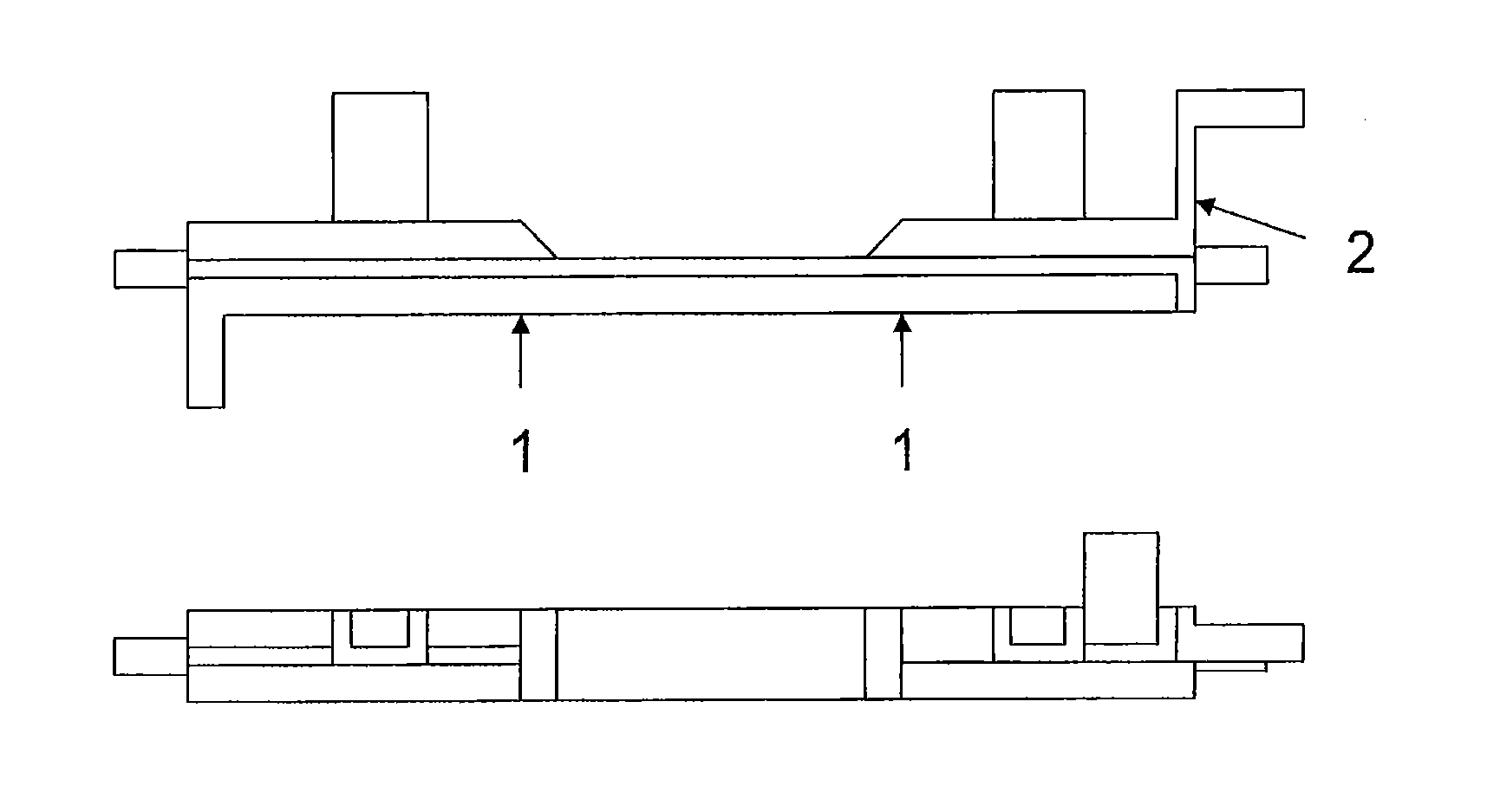
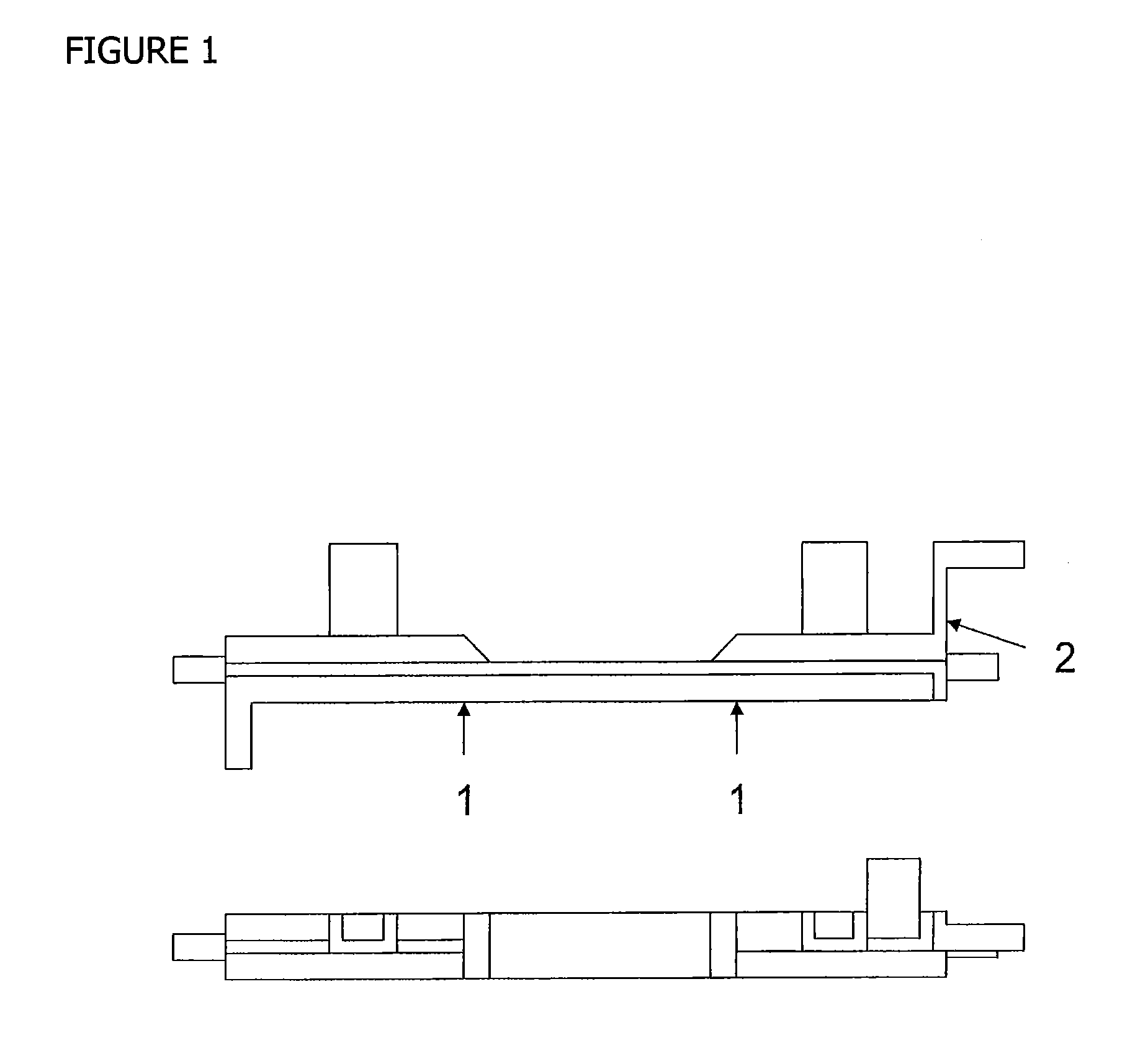
Image

Examples
example 1
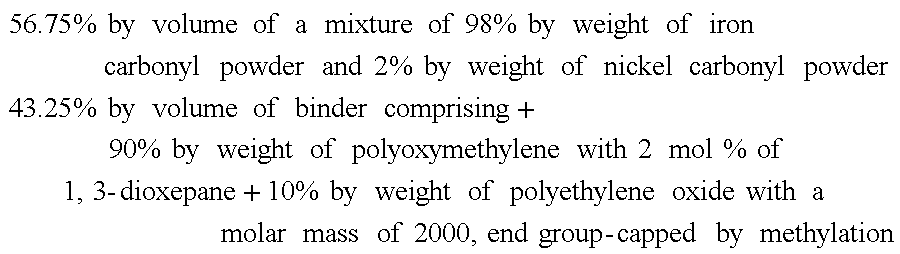
[0083]Molding composition 1 had the following composition:
56.75%byvolumeofamixtureof98%byweightofironcarbonylpowderand2%byweightofnickelcarbonylpowder43.25%byvolumeofbindercomprising+90%byweightofpolyoxymethylenewith2mol%of 1,3-dioxepane+10%byweightofpolyethyleneoxidewithamolarmassof2000,endgroup-cappedbymethylation
example 2
[0084]Molding composition 2 had the following composition:
56.75%byvolumeofamixtureof98%byweightofironcarbonylpowderand2%byweightofnickelcarbonylpowder43.25%byvolumeofbindercomprising+80%byweightofpolyoxymethylenewith2mol%of 1,3-dioxepane+20%byweightofpolyethyleneoxidewithamolarmassof2000,endgroup-cappedbymethylation
example 3
[0085]Molding composition 3 had the following composition:
56.75%byvolumeofamixtureof98%byweightofironcarbonylpowderand2%byweightofnickelcarbonylpowder43.25%byvolumeofbindercomprising+50%byweightofpolyoxymethylenewith2mol%of 1,3-dioxepane+50%byweightofpolyethyleneoxidewithamolarmassof2000,endgroup-cappedbymethylation
PUM
| Property | Measurement | Unit |
|---|---|---|
| Percent by volume | aaaaa | aaaaa |
| Percent by volume | aaaaa | aaaaa |
| Percent by volume | aaaaa | aaaaa |
Abstract
Description
Claims
Application Information