Apparatus for producing electric or mechanical energy from wave motion

a technology of electric or mechanical energy and apparatus, which is applied in the direction of sea energy generation, friction gearings, engine fuctions, etc., can solve the problems of limited installation and performance, only 50% of the development or capacity of the exploitation of wave motion, and problems relating at least to their efficiency, etc., to achieve low economic investment, high efficiency, and ductile and versatile

Inactive Publication Date: 2012-09-20
A P SISTEM DI PICCININI ALBERTO +1
View PDF7 Cites 23 Cited by
  • Summary
  • Abstract
  • Description
  • Claims
  • Application Information

AI Technical Summary

Benefits of technology

[0019]This apparatus being however ductile and versatile, enables energy to be obtained with a high efficiency, low economic investments and limited need for maintenance, from renewable sources such as the natural wave motion in oceans and seas or also artificial created in artificial basins, without however excluding mechanical sources such as lifts, cable railways and the like.
[0020]Furthermore, the apparatus of the invention is modulatable, it can be inserted in an ambient with wave motions of any amplitude, height and season, in that they have yields clearly superior to those of the systems known up to now. In addition it is auto-levelling; able that is to automatically adapt itself to the variations of the seas and their level and to follow within certain limits also the lengths of the waves without losing efficiency.

Problems solved by technology

In this field of the technique, systems for a production of energy are already known starting from the wave-motion, which however, even if the prerogatives often get elated, they have limits as regards to installation and performance in particular due to their high costs and long amortization periods, as well as in the real productivity capacity.
Some of the methods used up to now for the production of energy from wave motion, or tidal energy, have problems connected at least to their efficiency.
In fact usually the exploitation of the wave motion is only 50% of its development or capacity, as it is usually limited to the descending or ascending movement of the waves.
The system seems to be advantageous in a so called “oceanic” ambient, that is to say in the presence of considerably high waves, but it cannot have high yields with small applications, in that, passing from a pump followed by a water turbine, substantial loss in loads take place and consequently the power.
In a limited context in fact it would be expensive and with a low yield in the production of energy.
Therefore 50% of the possible profile yield of the wave is lost, as the rising up is used to reload the system, reaccelerating the genera tor which otherwise tends to slow down.
In this system, however, the moderate motion limits the capacity of the system.
In fact, a very low linear speed developed by the wave, corresponds to very low energetic transformation yields.
Also in this case, the stroke becomes a factor that greatly limits the performance.
In fact in the presence of waves higher than the length of the piston rod, they are not adequately exploited for energetic production.
Furthermore, the oleodynamic or mechanical deferments present develop friction and substantial losses in capacity.
However, given its configuration, this system cannot be ma de watertight so as to be placed directly in the water, so much so that it is described to be installed out of the water, on the land.

Method used


Image

  • Apparatus for producing electric or mechanical energy from wave motion
  • Apparatus for producing electric or mechanical energy from wave motion
  • Apparatus for producing electric or mechanical energy from wave motion

Examples


Embodiment Construction

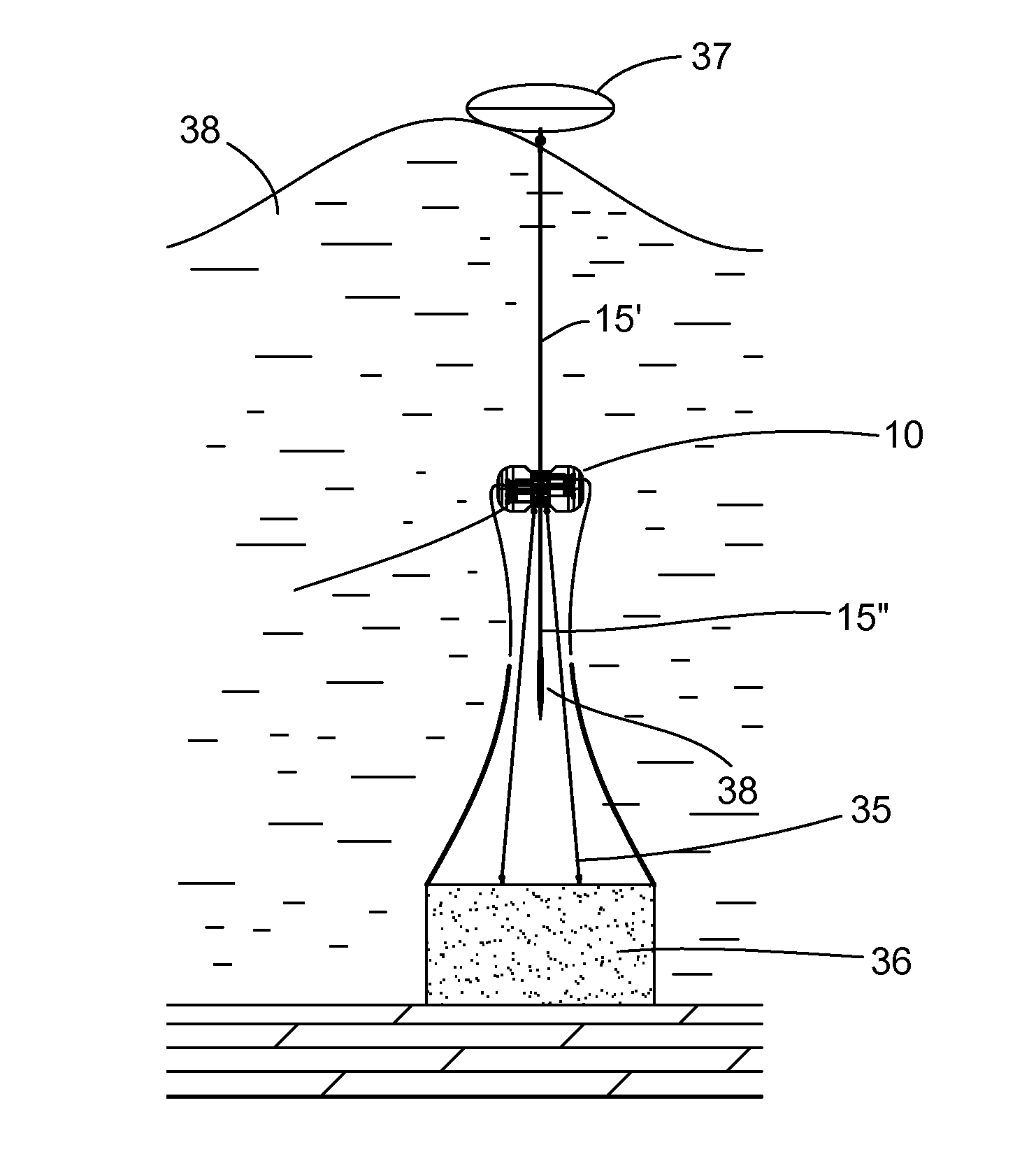
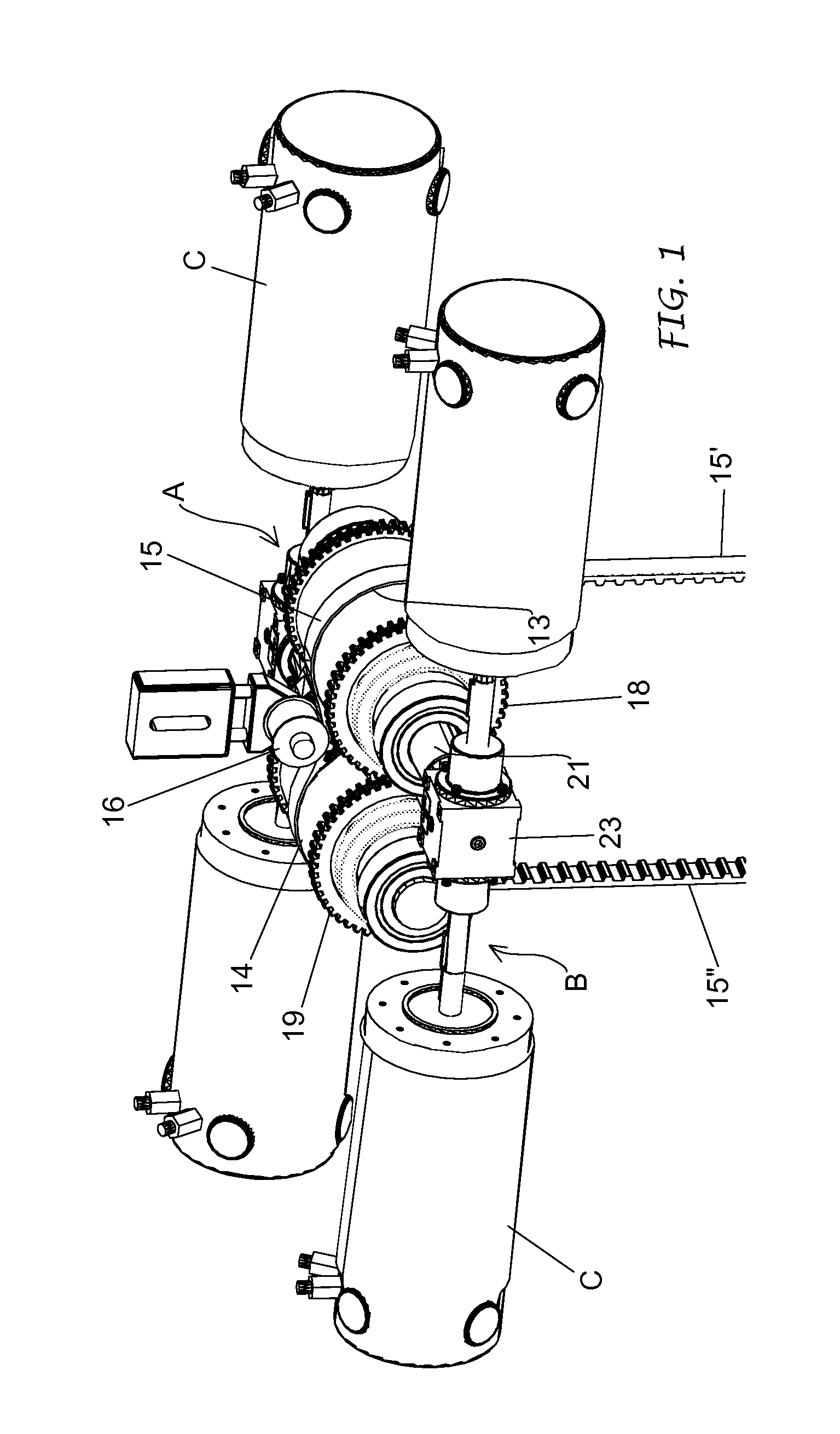
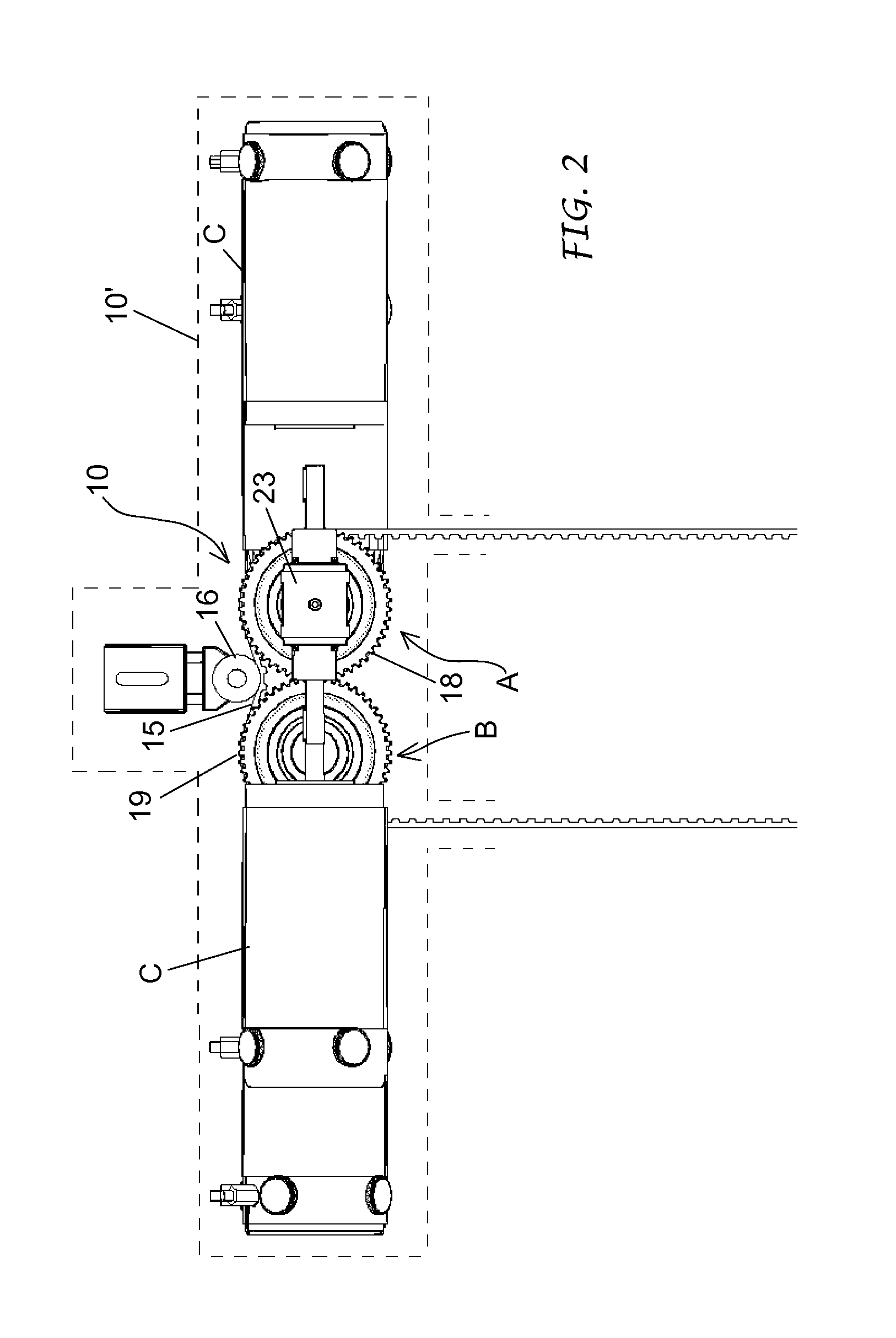
[0033]The apparatus of the invention represented in FIGS. 1-5 and indicated globally by 10 basically comprises two operating units A and B, parallel side by side, designed for a production of electric energy, each one by means of one or more power generators C, starting from an alternating linear motion or, more in particular, from the movement of the surface of the water in oceans, seas and lakes.

[0034]The apparatus comprises two main or driving shafts 11, 12, one for each operating unit A and B, parallel and supported in rotation on respective bearings 11′, 12′ carried by a crankcase or casing 10′.

[0035]In the example represented, a first operating unit A is fixed to the main shaft 11, and consequently rotating with it, a driving wheel 13 positioned in correspondence, that is coplanar, to a corresponding driving wheel 14 fixed to the main shaft 12 of the other operating unit B. The two driving wheels 13, 14 can be made up of gear wheels or driving pulleys, but they are however rad...


PUM


Abstract

The invention concerns an apparatus for generating power, in particular electric energy, from wave motion in water basins. It comprises at least an operating unit, including gearing provided for unidirectional rotation and to continuously operate at least one power generator in response to the movements of a control element susceptible to alternating linear movements deriving from the wave motion. Each operating unit comprises at least a main or driving shaft (11, 12; 11b) so lidly carrying a driving wheel (13, 14; 13b) engaged and placed in rotation by said linear control element (15, 15b) and at least two driven shafts (21, 22; 21b, 22b) operated by the main shaft through a unidirectional drive mechanism (20, 20b) and each connectable to at least a power generator.

Description

FIELD OF THE INVENTION[0001]The present invention relates to a system composed of mechanical members for the transformation of a natural or artificial linear or alternating wave motion into a unidirectional rotary motion, in particular for the production of electrical or mechanical energy.State of the Technique[0002]Mechanical devices for the transformation of an alternating motion into a unidirectional rotary motion of the type assimilable in general, and generally simply defined as being freewheel, are well known. They are used as operation systems for transmitting a unidirectional rotation motion to any coupler or rotating system also when the motion at the source is alternating or discontinuous.[0003]The system proposed here, is configured and is run to take advantage of the wave-motion with the help of at least a floating body , or buoy, specifically for generating electric energy directly from a renewable source, and to re-enter therefore between the apparatus for a production...

Claims


Application Information

Patent Timeline
Patent Type & Authority Applications(United States)
IPC IPC(8): F03B13/14
CPCF03B13/1865F03B13/1885Y02E10/38F05B2260/4021F05B2260/504F03B13/20Y02E10/30F16H19/06F05B2240/97F05B2240/93
Inventor PICCININI, GIUSEPPE RAOUL
Owner A P SISTEM DI PICCININI ALBERTO
Why Eureka
Try Eureka