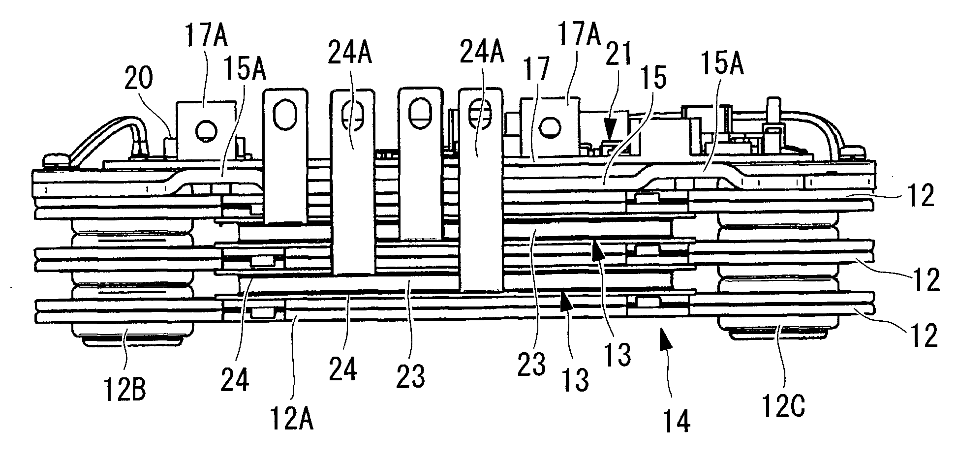
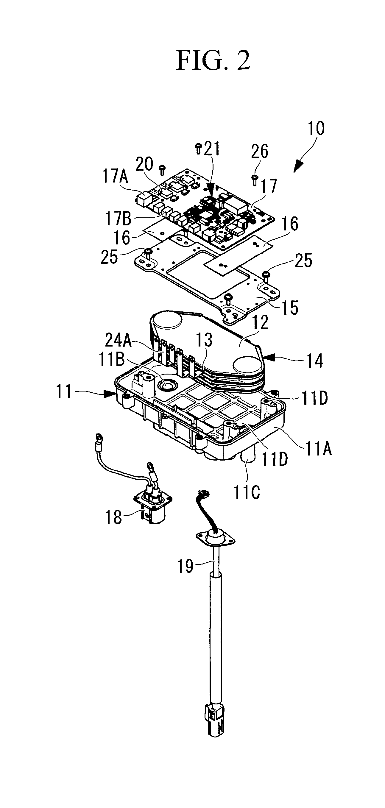
[0013]According to the present invention, the plurality of flat heat exchanger tubes are stacked on each other, and the PTC heaters are respectively incorporated between the flat tube parts thereof. In this state, the flat heat exchanger tubes and the PTC heaters are pressed by the heat exchanger holding member, to be thereby brought into
close contact with each other. The control board having the surface on which the
control circuit is mounted is placed above the heat exchanger holding member, the control circuit including the heat-generating electrical component that controls the PTC heaters. The control board includes the
heat penetration part that is formed so as to pass through the control board correspondingly to the mounting position of the heat-generating electrical component, the heat penetration part being made of the highly thermally conductive material, and the heat-generating electrical component is mounted so as to be cooled via the heat penetration part by the heat exchanger holding member functioning as the
heat sink. Hence, the PTC heaters are respectively sandwiched and stacked between the plurality of flat heat exchanger tubes, and the flat heat exchanger tubes and the PTC heaters are pressed by the heat exchanger holding member. As a result, the flat heat exchanger tubes and the PTC heaters can be incorporated in
close contact with each other. Accordingly, the
thermal contact resistance between the flat heat exchanger tubes and the PTC heaters can be reduced, and the
heat transfer efficiency can be increased, so that the performance of the heat medium heating apparatus can be enhanced. Further, because the flat heat exchanger tubes and the PTC heaters are stacked into a multilayer structure, the planar area thereof can be reduced, and the heat exchanger module and even the heat medium heating apparatus can be compactified. In addition, because the control board is provided above the heat exchanger holding member that presses the flat heat exchanger tubes from one side thereof, the heat-generating electrical component mounted on the control board can be efficiently cooled via the heat penetration part by the heat exchanger holding member functioning as the
heat sink. Accordingly, easy incorporation of the control board and the reliability thereof against heat can be ensured, and the need to provide a dedicated board accommodating box and a large-sized heat medium circulating box can be eliminated, leading to a reduction in size and weight of the heat medium heating apparatus as well as lower costs thereof.
[0015]According to the present invention, the heat exchanger holding member is made of the aluminum
alloy plate. Therefore, heat from the heat-generating electrical component on the control board is transferred through the heat penetration part to the heat exchanger holding member made of the light aluminum
alloy plate having excellent
thermal conductivity, and the heat is then transferred to the heat exchanger holding member cooled by the flat heat exchanger tubes, whereby the heat-generating electrical component can be cooled. Accordingly, the cooling performance of the heat-generating electrical component mounted on the surface of the control board can be enhanced by the heat exchanger holding member functioning as the
heat sink, the reliability against heat can be increased, and the reduction in weight can be retained.
[0017]According to the present invention, the spacer member is interposed between the heat exchanger holding member and the heat penetration part of the control board, the spacer member being made of the highly thermally conductive material and having the predetermined thickness. Therefore, when the control board is placed above the heat exchanger holding member, even if a given interval therebetween needs to be ensured, the spacer member made of the highly thermally conductive material such as an aluminum
alloy plate and having the predetermined thickness is interposed therebetween, whereby the heat exchanger holding member can function as the heat sink to thereby reliably cool the heat-generating electrical component mounted on the surface of the control board. Accordingly, even in such a case, the cooling performance for the control board can be enhanced, the reliability against heat can be ensured, and the reduction in weight can be retained.
[0019]According to the present invention, the plurality of terminal blocks are arranged along one side of the surface of the control board, and the plurality of terminals extending from one ends of
electrode plates provided on both the surfaces of the PTC heaters are respectively connectable directly to the terminal blocks. Therefore, the control board having the surface on which the control circuit including the heat-generating electrical component that controls the PTC heaters is mounted can be electrically connected to the
electrode plates provided on both the surfaces of the PTC heaters, by respectively connecting, on the surface side of the control board, the terminals extending from the one ends of the
electrode plates directly to the terminal blocks arranged along the one side of the surface of the control board. Accordingly, the work of electrically connecting the control board to the electrode plates can be facilitated, and the assembling properties can be thus improved. Further, the need to provide a harness is eliminated, leading to a reduction in the number of components, more simplified configuration, and lower costs.
[0021]According to the present invention, the plurality of flat heat exchanger tubes and the PTC heaters in the alternately stacked state are fastened to the inner bottom surface of the casing by the heat exchanger holding member, the casing including the heat medium inlet and the heat medium outlet respectively communicated with the inlet header part and the outlet header part. Therefore, the flat heat exchanger tubes and the PTC heaters alternately stacked on each other are fastened to the inner bottom surface of the casing by the heat exchanger holding member, whereby the flat heat exchanger tubes and the PTC heaters can be fixed in close contact with each other. Accordingly, the flat heat exchanger tubes and the PTC heaters can be stacked on each other such that the close contact therebetween is easily and reliably increased in the course of the stacking. Hence, the
thermal contact resistance between the flat heat exchanger tubes and the PTC heaters can be reduced, the heat transfer performance can be thus increased, and the assembling properties can be improved. In addition, the casing does not necessarily need to be made of an aluminum alloy material having a
heat resistance property and a heat transfer property, and may be made of a resin material, leading to a reduction in weight as well as lower costs.
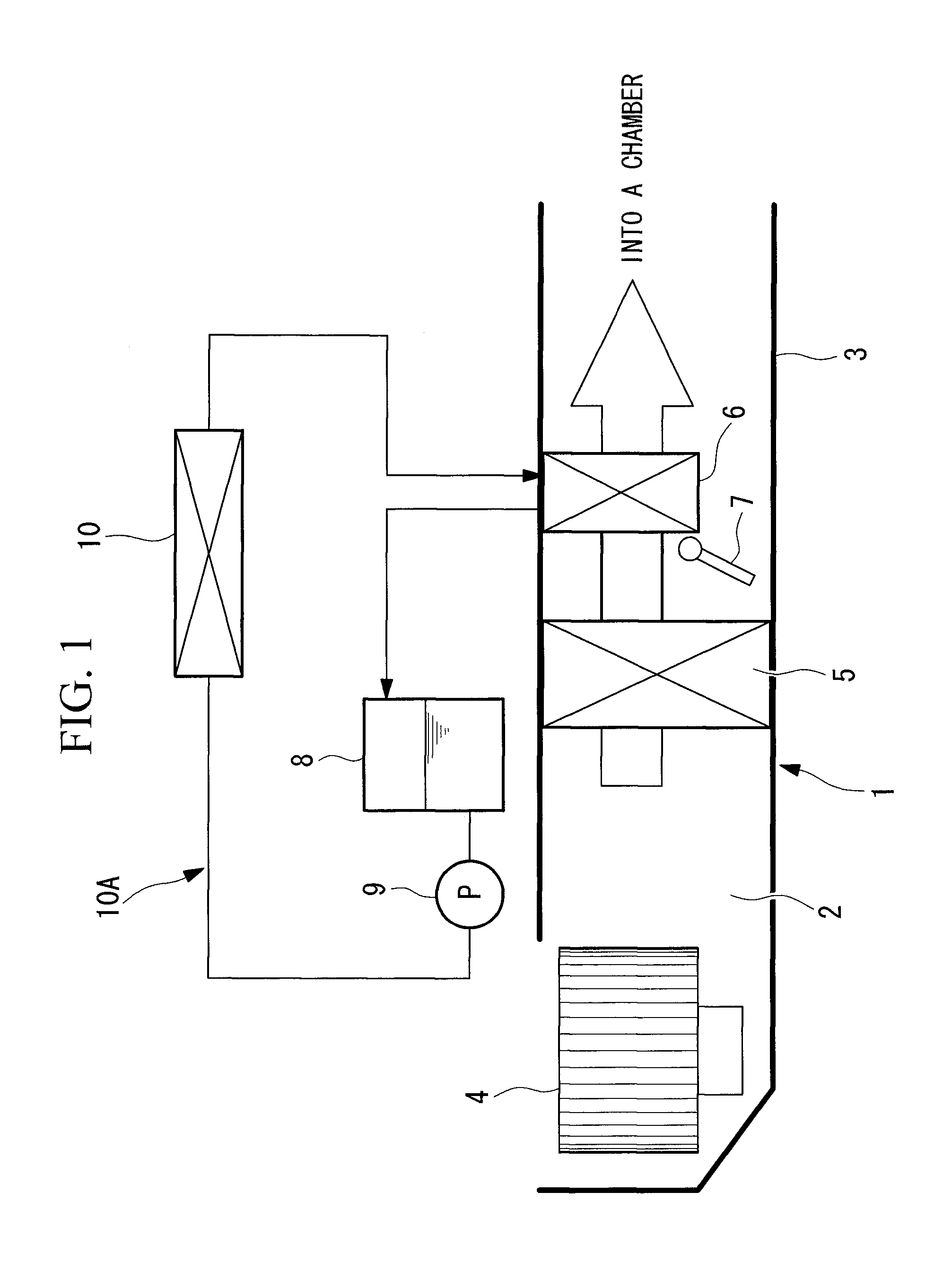
[0023]According to the present invention, the heat medium heated by the heat medium heating apparatus having any of the above-mentioned features can circulate through the heat radiator placed in the air flow passage. Therefore, the heat medium to be supplied to the heat radiator provided in the air flow passage can be heated by the heat medium heating apparatus having the
reduced size, the reduced weight, and the enhanced performance as described above. Accordingly, the air-conditioning performance, particularly, the heating performance of the vehicular air-conditioning
system can be enhanced, and the mounting properties of the air-conditioning
system onto a vehicle can be enhanced.


