
Method and installation for producing cement clinker

a cement clinker and installation method technology, applied in the direction of furnaces, lighting and heating apparatuses, furnace types, etc., can solve the problems of increased energy requirements, increased exhaust gas temperature, and change in flame shape and temperature distribution, and achieve high moisture levels, without clinker production limitations

Inactive Publication Date: 2012-10-04
THYSSENKRUPP IND SOLUTIONS AG
View PDF6 Cites 2 Cited by
  • Summary
  • Abstract
  • Description
  • Claims
  • Application Information

AI Technical Summary

Benefits of technology

[0007]An object of the invention is therefore to improve the method and the installation for producing cement clinker using secondary fuels with high levels of moisture, without complex cleaning of the excess exhaust gas from the dryer being required and without the clinker production being limited.
[0017]The SCR catalytic convertor is generally constructed as a honeycomb type or plate type catalytic convertor with very small openings of approximately 10 mm. The very high dust loads of approximately 70 g / Nm3 which are present downstream of the preheater can therefore lead to clogging of the channels. At relatively high exhaust gas temperatures, in particular greater than 400° C., as often found as a result of the combustion of high secondary fuel rates downstream of the preheater, there is produced a higher durability of the dusts compared with the dust properties at lower temperatures of, for example, 350° C., which are produced when conventional fuels are used. The ability to flow is reduced accordingly and the danger of clogging increases.
[0018]Owing to the use of the drying exhaust gas produced during the drying operation and / or exhaust vapour condensate for exhaust gas quenching upstream of the SCR catalytic convertor, the danger of clogging in the SCR catalytic convertor can be reduced. Furthermore, the supply of the drying exhaust gas and / or the exhaust vapour condensate has the advantage that carbon-containing odorous substances contained are oxidised with oxygen in the SCR catalytic convertor and the ammonia contained reduces the nitrogen oxides so that the quantity of ammonia water supplied to the NOx reduction can be reduced accordingly.
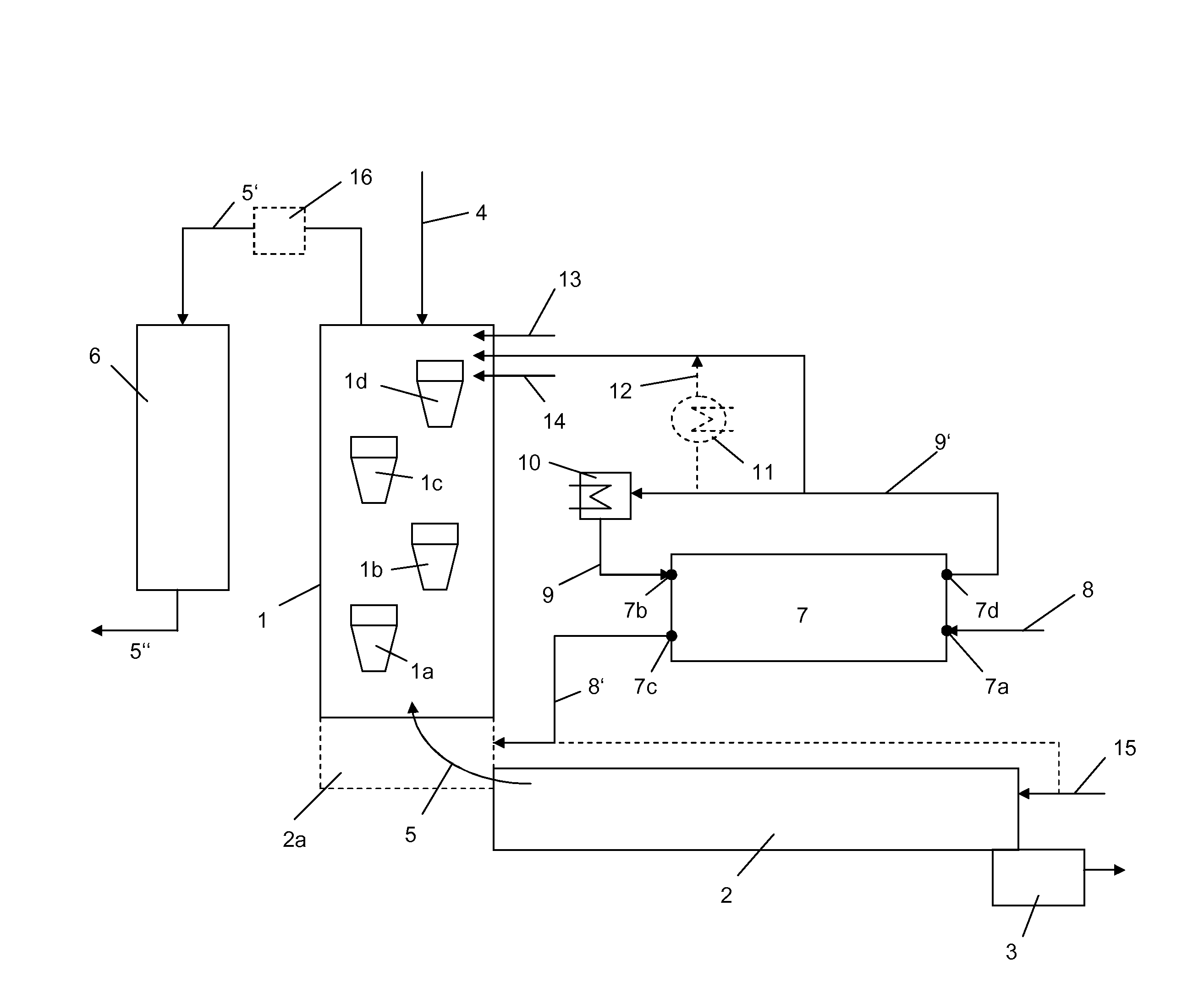
[0021]The exhaust gas or exhaust vapour condensate from the replacement fuel dryer is supplied upstream of the SCR catalytic convertor in order to reduce the preheater exhaust gases upstream of the SCR catalytic convertor to temperatures of between 280 and 400° C. and preferably to temperatures of between 330 and 370° C. and thereby to reduce the risk of the SCR catalytic convertor becoming clogged. The quenching is preferably carried out in the uppermost cyclone stage of a preheater which has a plurality of cyclone stages which are arranged one above the other with exhaust vapour condensate from the replacement fuel dryer since the highest cooling output is thereby achieved.
[0022]On the SCR catalytic convertor, in addition to a conversion of NOx with NH3 which is supplied as a reduction solution to N2, there is also carried out a simultaneous conversion (oxidation) of hydrocarbons. Owing to the combination of the exhaust gas or exhaust vapour removal with the exhaust gas quenching, no additional complex cleaning of the exhaust gas flows of the dryer occurring is consequently necessary and the requirement for fresh water and / or cooling gas for exhaust gas quenching can be reduced.

Problems solved by technology

However, the use of replacement fuels leads to a change in the flame shape and the temperature distribution in the kiln and thereby to an increased energy requirement, which results in correspondingly higher exhaust gas temperatures.
However, the introduction leads to an increasing volume flow of exhaust gas, which requires greater sizing of the preheater or limits the production in existing installations.
However, the complexity of the installation increases significantly as a result.

Method used


Image

  • Method and installation for producing cement clinker
  • Method and installation for producing cement clinker

Examples


Embodiment Construction

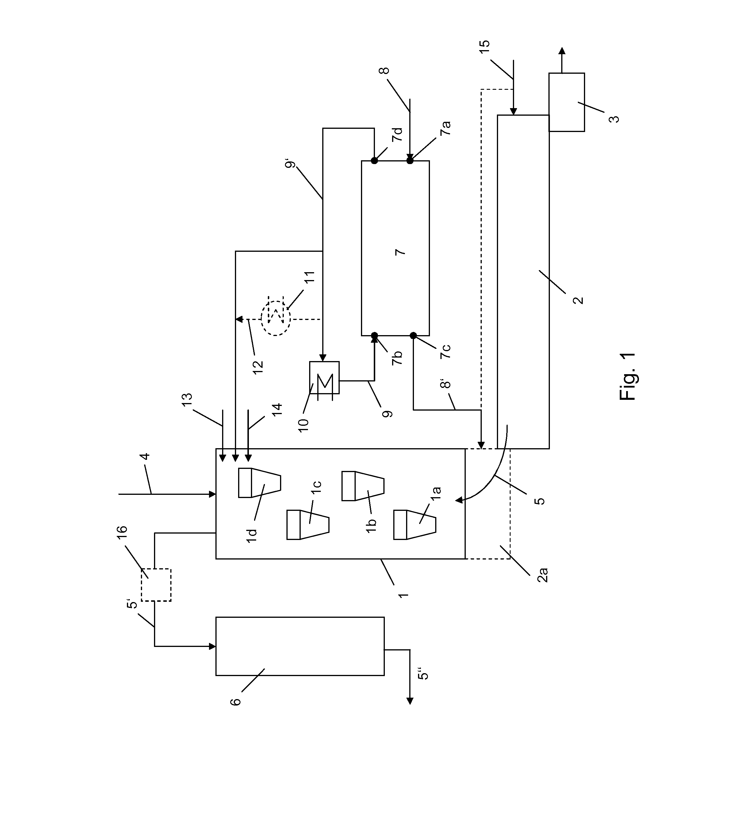
[0026]The installation has a thermal processing device which comprises in the illustrated embodiment a preheater 1, a kiln and a cooler 3. The preheater 1 is constructed as a suspension type heat exchanger with a plurality of cyclone stages la to ld which are arranged one above the other, cement raw meal 4 being preheated in counter-current to exhaust gases 5 which are produced during the clinker production and the calcination. An optional calcinator 2a for calcination of the preheated cement raw meal is further arranged between the preheater 1 and kiln 2.

[0027]The cement raw meal which is burnt to form cement clinker in the kiln 2 is subsequently cooled in the cooler 3.

[0028]The exhaust gas 5′ which leaves the preheater 1 is subsequently cleaned in an SCR catalytic convertor 6, the cleaned exhaust gas 5″ being used in a drying milling installation (not illustrated) or being supplied directly to a process filter. Between the preheater 1 and the SCR catalytic convertor 6 it is option...


PUM

PropertyMeasurementUnit
temperatureaaaaaaaaaa

Abstract

During the production of cement clinker by preheating cement raw meal in a preheater and calcining and sintering the preheated cement raw meal, the exhaust gases which are produced during the calcination and the sintering process are used for preheating and are subsequently cleaned in an SCR catalytic convertor. There are used during the clinker production replacement fuels which contain carbon-containing odorous substances and / or ammonia-containing compounds which are previously dried, wherein a drying exhaust gas which is produced during the drying operation and / or exhaust vapour condensate being used at least partially for exhaust gas quenching upstream of the SCR catalytic convertor, and the carbon-containing odorous substances and / or ammonia-containing compounds in the drying exhaust gas and / or exhaust vapour condensate being converted on the SCR catalytic convertor.

Description

TECHNICAL FIELD[0001]The invention relates to a method and an installation for producing cement clinker by preheating and calcining cement raw meal in a thermal processing device, the exhaust gases which are produced during the clinker production being used for preheating.BACKGROUND OF THE INVENTION[0002]The burning of cement clinker is currently carried out almost exclusively in cylindrical rotary kiln installations at temperatures of around 1,450° C. The energy required for burning is generally provided by burning conventional fuels, such as coal, in the main burner. For cost reasons, the conventional fuels are being increasingly replaced in practice by replacement fuels. However, the use of replacement fuels leads to a change in the flame shape and the temperature distribution in the kiln and thereby to an increased energy requirement, which results in correspondingly higher exhaust gas temperatures.[0003]The cement raw meal is heated and calcined in a heat exchanger which is usu...

Claims


Application Information

Patent Timeline
Patent Type & Authority Applications(United States)
IPC IPC(8): C04B2/10
CPCC04B7/364C04B7/4423C04B7/4438F27B7/2033C04B7/4407F27B7/20C04B7/365C04B7/436C04B7/475F27D17/008Y02P40/125
Inventor STENDER, TIMODINKOVA, ANNA
Owner THYSSENKRUPP IND SOLUTIONS AG
Learn More