
Cascaded stack with gas flow recycle in the first stage

a stack and cascade technology, applied in the field of cascade stack recycling systems, can solve the problems of negative impact on performance and durability, relatively expensive manufacturing of membrane electrode assemblies, and high cost of catalysts, and achieve the effect of increasing the moisture level

Active Publication Date: 2007-05-03
GM GLOBAL TECH OPERATIONS LLC
View PDF10 Cites 15 Cited by
  • Summary
  • Abstract
  • Description
  • Claims
  • Application Information

AI Technical Summary

Benefits of technology

[0050] Some of the benefits of the present invention include, without limitation: (1) humidified inlet gas for all stages of the cascaded stack, which is expected to increase performance and durability; (2) cost reduction by eliminating the need for expensive external humidification devices (e.g., a water vapor transfer unit); (3) reducing the number of components in the fuel cell system, which reduces cost, system size and controls effort; and (4) reduced start-stop degradation by using a diluted gas supply.

Problems solved by technology

The catalytic particles are typically costly precious metal particles.
These membrane electrode assemblies are relatively expensive to manufacture and require certain conditions, including proper water management and humidification, and control of catalyst fouling constituents such as carbon monoxide (CO), for effective operation.
The inhomogeneous power distribution might lead to hot spots in some areas, and to excessive water accumulation in other areas, which again has a negative affect on performance and durability.
Furthermore, humidification devices have several disadvantages, especially for automotive applications of the fuel cell stack, as they are heavy, expensive, and sometimes, due to the water they contain, subject to freezing at low ambient temperatures.
A disadvantage is the need for a recirculation pump, the power consumption of the pump and the humidity gradient in a stack along the channel.
The feed gas, however, is suggested to be the oxidant, and is dry, which might lead to performance degradation at both gas inlets.

Method used

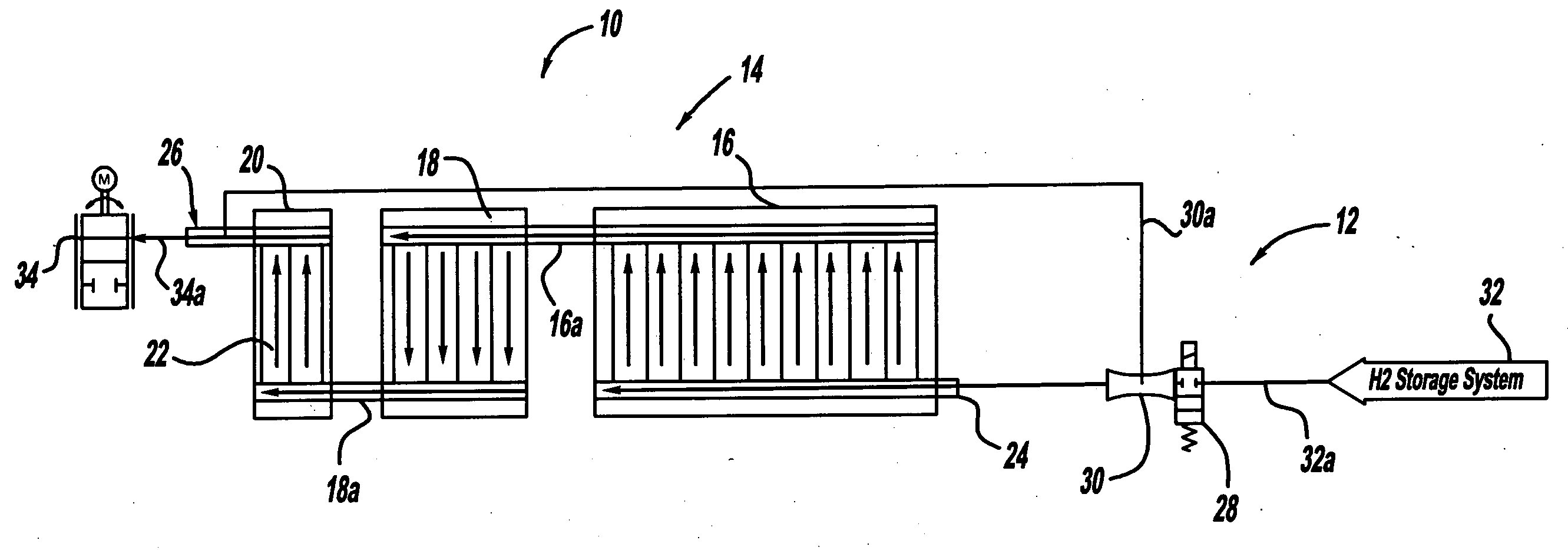
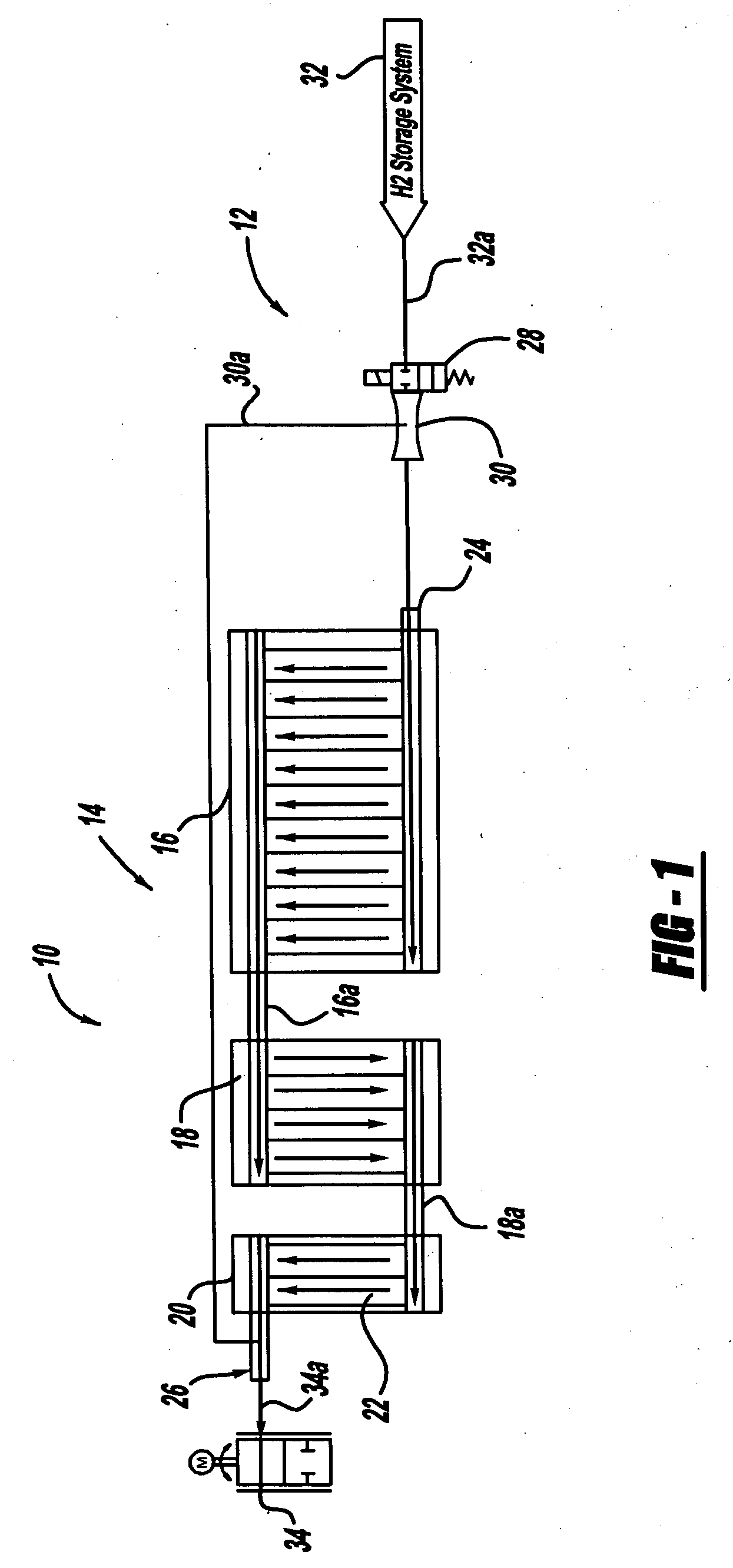

Image

  • Cascaded stack with gas flow recycle in the first stage
  • Cascaded stack with gas flow recycle in the first stage
  • Cascaded stack with gas flow recycle in the first stage

Examples


Embodiment Construction

[0020] The following description of the preferred embodiment(s) is merely exemplary in nature and is in no way intended to limit the invention, its application, or uses.

[0021] By “fluid,” as that term is used herein, it is meant any gaseous and / or liquid material, such as but not limited to liquid water, water vapor, and combinations thereof.

[0022] Referring to FIG. 1, there is shown a schematic illustration of a three stack fuel cell system 10 having a humidification / gas recirculation system 12 operably associated with the stack anode flow 14 side, in accordance with one embodiment of the present invention.

[0023] The fuel cell system 10 includes three fuel cell stacks, 16, 18, 20, respectively, that are in fluid communication with one another, or at least with an adjacent fuel cell stack. The fuel cell stacks 16, 18, 20, respectively, are comprised of a number of individual fuel cell elements 22. The number of fuel cell elements 22 can be varied among the fuel cell stacks 16, 18...


PUM

PropertyMeasurementUnit
non-electrically conductiveaaaaaaaaaa
electrically conductiveaaaaaaaaaa
thermally conductiveaaaaaaaaaa

Abstract

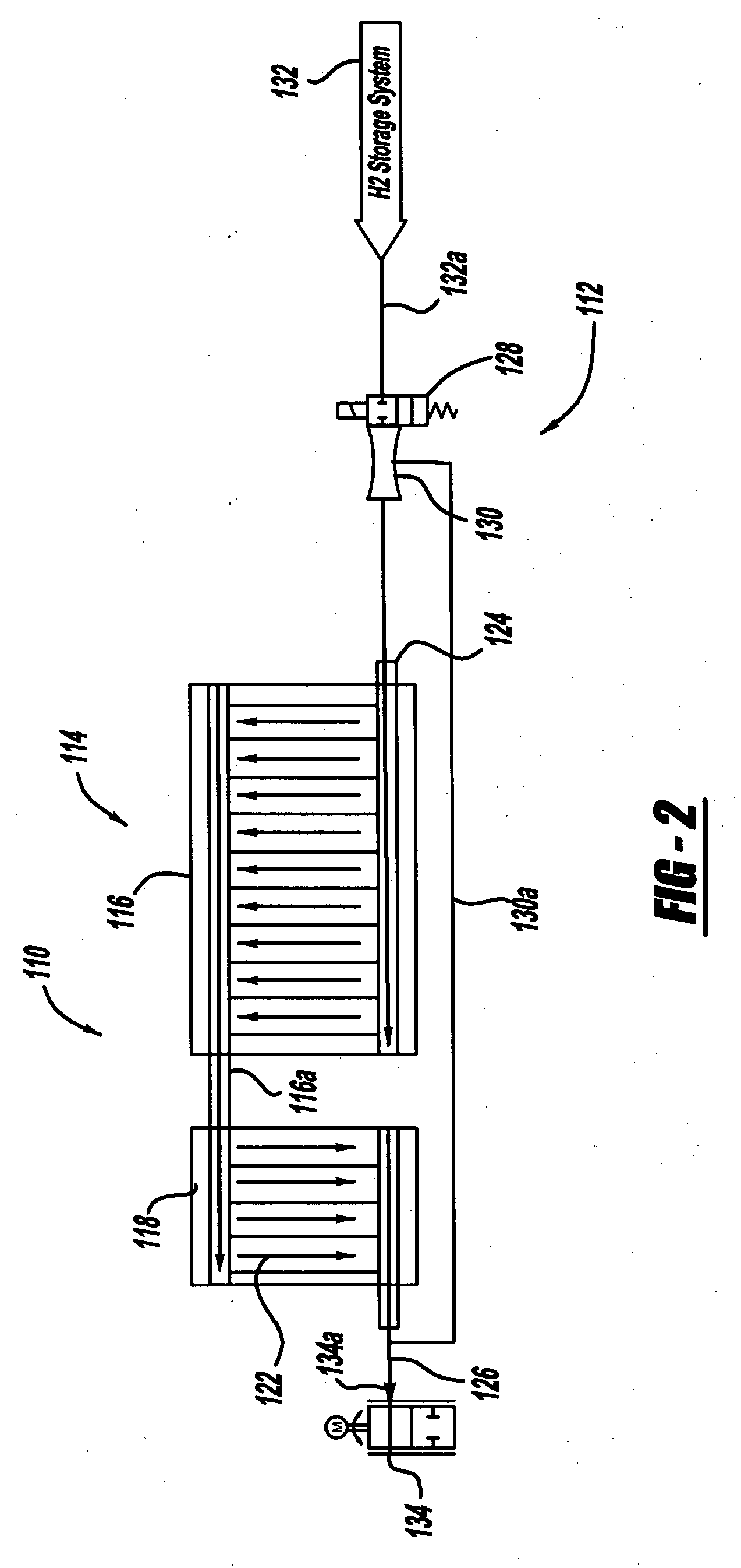
A fuel cell system including a humidification system is described. The humidification system employs a recycling system that recycles relatively humid gas exhausted from a multistage fuel cell stack, either on the anode and / or cathode side, and sends this relatively humid gas back to be combined with relatively dry supply gas, such as but not limited to hydrogen and / or air. The humidified supply gas mixture is then reintroduced into the first stage of the multistage fuel cell stack. A recirculation device, such as but not limited to a pump and / or an ejector, can be used to aid in moving the humid exhaust gas back through a recycle gas line to be combined with the supply gas.

Description

FIELD OF THE INVENTION [0001] The present invention relates generally to fuel cell systems, and more particularly to new and improved gas flow recycle systems for use in fuel cell systems. BACKGROUND OF THE INVENTION [0002] Fuel cells have been used as a power source in many applications. For example, fuel cells have been proposed for use in electrical vehicular power plants to replace internal combustion engines. In PEM-type fuel cells, hydrogen is supplied to the anode of the fuel cell and oxygen is supplied as the oxidant to the cathode. PEM fuel cells include a membrane electrode assembly (MEA) comprising a thin, proton transmissive, non-electrically conductive solid polymer electrolyte membrane having the anode catalyst on one of its faces and the cathode catalyst on the opposite face. The MEA is sandwiched between a pair of electrically conductive elements, sometimes referred to as the gas diffusion media components, that: (1) serve as current collectors for the anode and cath...

Claims


Application Information

Patent Timeline
Patent Type & Authority Applications(United States)
IPC IPC(8): H01M8/04H01M8/24
CPCH01M8/04097H01M8/04141H01M8/249Y02E60/50
Inventor SENNER, RALF
Owner GM GLOBAL TECH OPERATIONS LLC
Learn More