Control Valve and Variable Capacity Swash-Plate Type Compressor Provided with same

a control valve and variable capacity technology, applied in the direction of valve operating means/release devices, machines/engines, positive displacement liquid engines, etc., can solve the problems of complex structure of control valves and difficult assembly, and achieve the effect of reducing the production cost of compressors and simple compressor structures

Inactive Publication Date: 2012-10-04
SANDEN CORP
View PDF16 Cites 15 Cited by
  • Summary
  • Abstract
  • Description
  • Claims
  • Application Information

AI Technical Summary

Benefits of technology

[0026]Variable capacity swash-plate type compressors control the internal pressure of the crank chambers by using control valves each comprising a pressure sensitive unit for detecting refrigerant pressure and a solenoid unit for variably controlling the ope...

Problems solved by technology

Each of the control valves of Patent Documents No. 1 and No. 2 has a problem such that the control valve has a complicated struct...

Method used


Image

  • Control Valve and Variable Capacity Swash-Plate Type Compressor Provided with same
  • Control Valve and Variable Capacity Swash-Plate Type Compressor Provided with same
  • Control Valve and Variable Capacity Swash-Plate Type Compressor Provided with same

Examples


embodiment 1

Preferred Embodiment 1

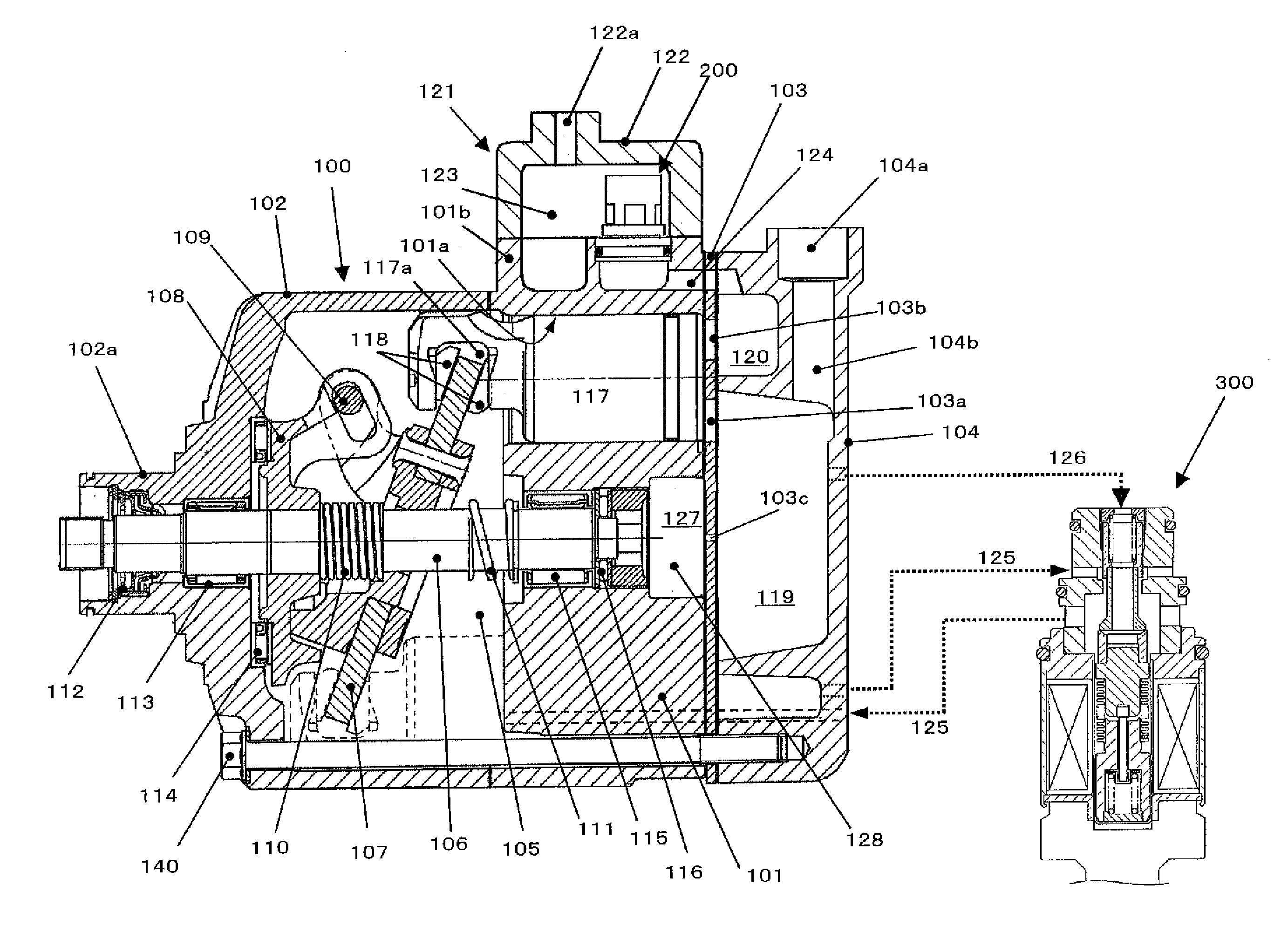
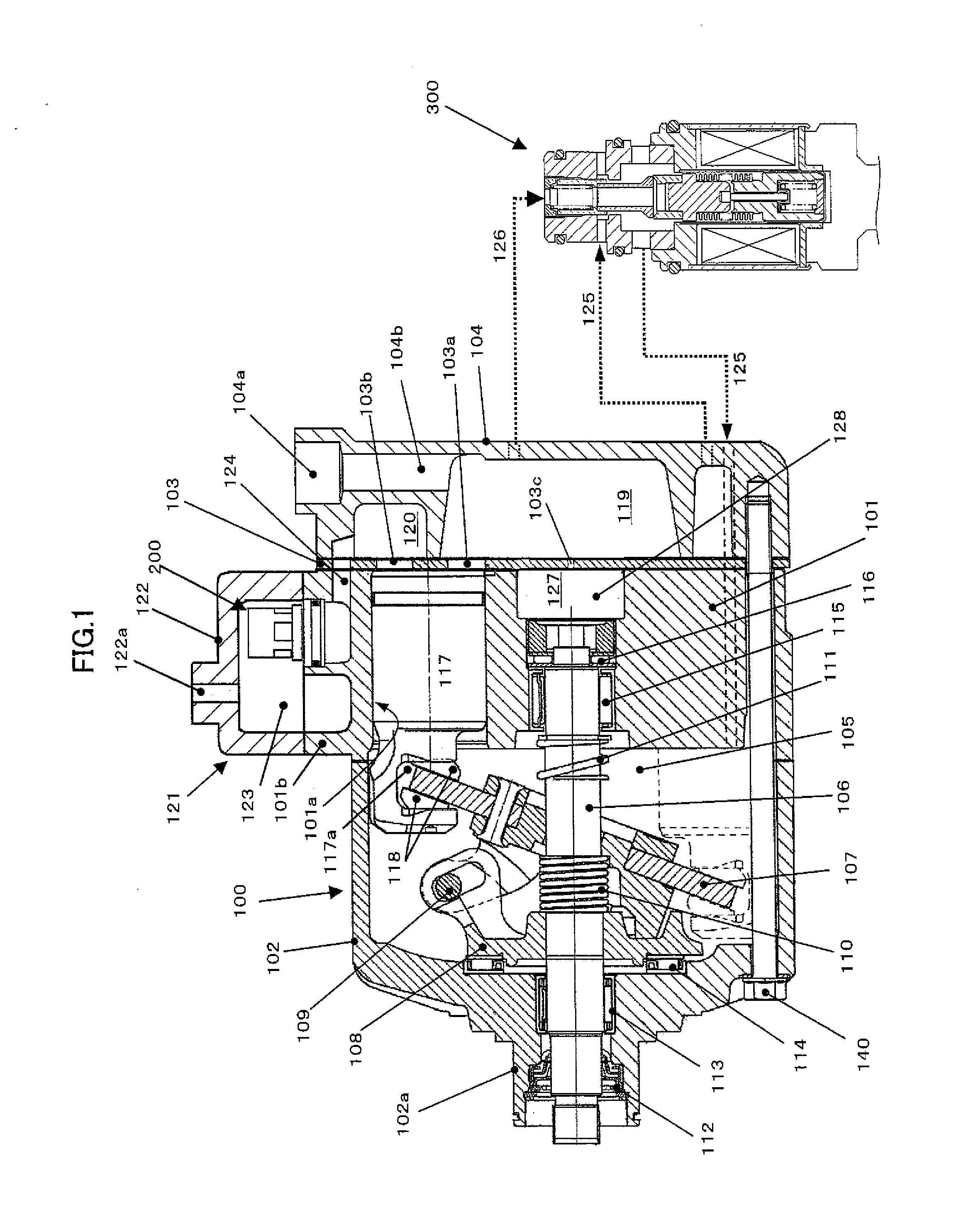
[0037]As shown in FIG. 1, a variable capacity swash-plate type compressor 100 comprises a cylinder block 101 provided with a plurality of cylinder bores 101a, a front housing 102 opposing one end of the cylinder block 101, and a cylinder head 104 opposing the other end of the cylinder block 101 with a valve plate 103 inserted between them.

[0038]The cylinder block 101 cooperates with the front housing 102 to define a crank chamber 105. A driving shaft 106 extends across the crank chamber 105. The driving shaft 106 passes through a swash plate 107 at the longitudinal middle. The swash plate 107 is connected to a rotor 108 fixed to the driving shaft 106 through a link 109. The driving shaft 106 supports the swash plate 107 variably at an inclination. A coil spring 110 is disposed between the rotor 108 and the swash plate 107 to force the swash plate 107 in a direction for decreasing the inclination to minimum level. A coil spring 111 is also provided. The coil spr...

embodiment 2

Preferred Embodiment 2

[0088]FIG. 4 shows a control valve 400 which is a variation of the control valve 300 shown in FIG. 2. In the control valve 400, the movable core of the solenoid unit is divided into a first movable core 411 forming a movable end member of a pressure sensitive unit 410 and a second movable core 430 disposed adjacent to the first movable core 411 and forced by a spring 420 in the opening direction.

[0089]When electric current is applied to the coil 362, the second movable core 430 is attracted by and united with the first movable core 411 to form a movable end member of the pressure sensitive unit, thereby performing the same operation as the control valve 300 shown in FIG. 2. In the control valve 400, the solenoid housing 350, the plate 361, the small diameter portion 370b of the sleeve 370, the end member 383, the first movable core, i.e., the end member 411, and the second movable core 430 cooperate to form a magnetic circuit. The operation characteristic of th...


PUM


Abstract

[Object of the Invention] An object of the present invention is to provide a control valve that accommodates a pressure sensitive unit in a solenoid unit and is of simple structure.
[Disclosure of the Invention] A control valve for opening and closing a fluid passage comprises a pressure sensitive unit provided with a bellows for receiving outside fluid pressure to expand and retract, a valve body for opening and closing a fluid passage in response to the expansion and retraction of the bellows, and a solenoid unit for applying electromagnetic force to the valve body, wherein the pressure sensitive unit is disposed in the solenoid unit, the pressure sensitive unit comprises a movable end member made of ferromagnetic material at one end of the bellows and a fixed end member made of ferromagnetic material at the other end of the bellows, the movable end member and the fixed end member oppose each other with a predetermined distance disposed between them, and the movable end member and the fixed end member form a part of the magnetic circuit of the solenoid unit.

Description

TECHNICAL FIELD[0001]The present invention relates to a control valve for opening and closing a fluid passage.BACKGROUND ART[0002]Patent Documents No. 1 and No. 2 teach control valves for opening and closing a fluid passage each comprising a pressure sensitive unit provided with a bellows for receiving outside fluid pressure to expand and retract, a valve body for opening and closing a fluid passage in response to the expansion and retraction of the bellows, and a solenoid unit for applying electromagnetic force to the valve body, wherein the pressure sensitive unit is disposed in the solenoid unit. In the control valve of Patent Document No. 1, the pressure sensitive unit is disposed in the movable core of the solenoid unit. In the control valve of Patent Document No. 2, the pressure sensitive unit is disposed in the fixed core of the solenoid unit. The control valve is downsized by disposing the pressure sensitive unit in the solenoid unit.PRIOR ART DOCUMENTSPatent Documents[0003]...

Claims


Application Information

Patent Timeline
IPC IPC(8): F04B27/18F04B1/26F16K31/06
CPCF04B27/1804F04B2027/1813F04B2027/1854F04B2027/185F04B2027/1827F04B27/08F04B27/14F04B17/04
Inventor TAGUCHI, YUKIHIKO
Owner SANDEN CORP
Why Eureka
Try Eureka