
Component in processing chamber of substrate processing apparatus and method of measuring temperature of the component

Active Publication Date: 2012-10-04
TOKYO ELECTRON LTD
View PDF7 Cites 18 Cited by
  • Summary
  • Abstract
  • Description
  • Claims
  • Application Information

AI Technical Summary

Benefits of technology

[0011]The present invention provides a component in a processing chamber of a substrate processing apparatus and a method of measuring a temperature of the component, where a temperature is accurately measured by using a temperature measuring apparatus using an interference of a low-coherence light, even when a front surface and a rear surface are not parallel due to abrasion, or the like.

Problems solved by technology

Accordingly, when the measured target is worn away by plasma and the degree of parallelization of the surface and rear surface is no longer maintained, requirements of the measured target are not satisfied, and thus a temperature cannot be accurately measured.

Method used


Image

  • Component in processing chamber of substrate processing apparatus and method of measuring temperature of the component
  • Component in processing chamber of substrate processing apparatus and method of measuring temperature of the component
  • Component in processing chamber of substrate processing apparatus and method of measuring temperature of the component

Examples


first embodiment

[0080]FIGS. 5A through 5C are views schematically showing a configuration of the focus ring 25 according to the present invention, wherein FIG. 5A is a plan view, FIG. 5B is a cross-sectional view taken along a line A-A of FIG. 5A, and FIG. 5C is a cross-sectional view of a coating member 25d inserted onto the thin-walled portion 25T.

[0081]Referring to FIGS. 5A through 5C, the focus ring 25 includes the thin-walled portion 25T as a temperature measured portion. The thin-walled portion 25T is a thin-walled portion corresponding to a concave portion 25c formed on the top surface 25a of the focus ring 25 exposed to an abrasive atmosphere in an upper space (the processing chamber 15) of the chamber 11, and forms a part of the focus ring 25. The top surface 25Ta and the bottom surface 25Tb of the thin-walled portion 25T are parallel to each other, and a mirror-like finishing is performed on each of the top and bottom surfaces 25Ta and 25Tb. Also, the thin-walled portion 25T is of a const...

second embodiment

[0095]Next, the present invention will be described.

[0096]FIG. 7 is a cross-sectional view schematically showing a structure of a focus ring 65 according to a second embodiment of the present invention. In the focus ring 65, a temperature measured member 65T is buried in a body of the focus ring 65, and is covered by a part of the focus ring 65, and thus is protected from an abrasive atmosphere with plasma.

[0097]Referring to FIG. 7, the focus ring 65 is formed of, for example, silicon carbide (SiC), and the temperature measured member 65T is buried in a concave portion formed on a bottom surface. The temperature measured member 65T is formed of, for example, silicon (Si), quartz, or sapphire, has parallel top and bottom surfaces, and is mirror-like finished. A thickness of the temperature measured member 65T is, for example, equal to or more than 50 μm. When the thickness is lower than 50 μm, an interference waveform based on a reflection light from the top surface and an interferen...

third embodiment

[0107]Next, the present invention will be described.

[0108]FIG. 9 is a cross-sectional view schematically showing a configuration of a focus ring 85 according to a third embodiment of the present invention.

[0109]In FIG. 9, the focus ring 85 is formed by attaching a temperature measured member 85T formed of silicon (Si) on about half of a bottom surface of the focus ring 85 formed of silicon carbide (SiC) via a heat transfer sheet 85e. The temperature measured member 85T has a circle shape concentric with an outer peripheral portion of the focus ring 85, along the outer peripheral portion.

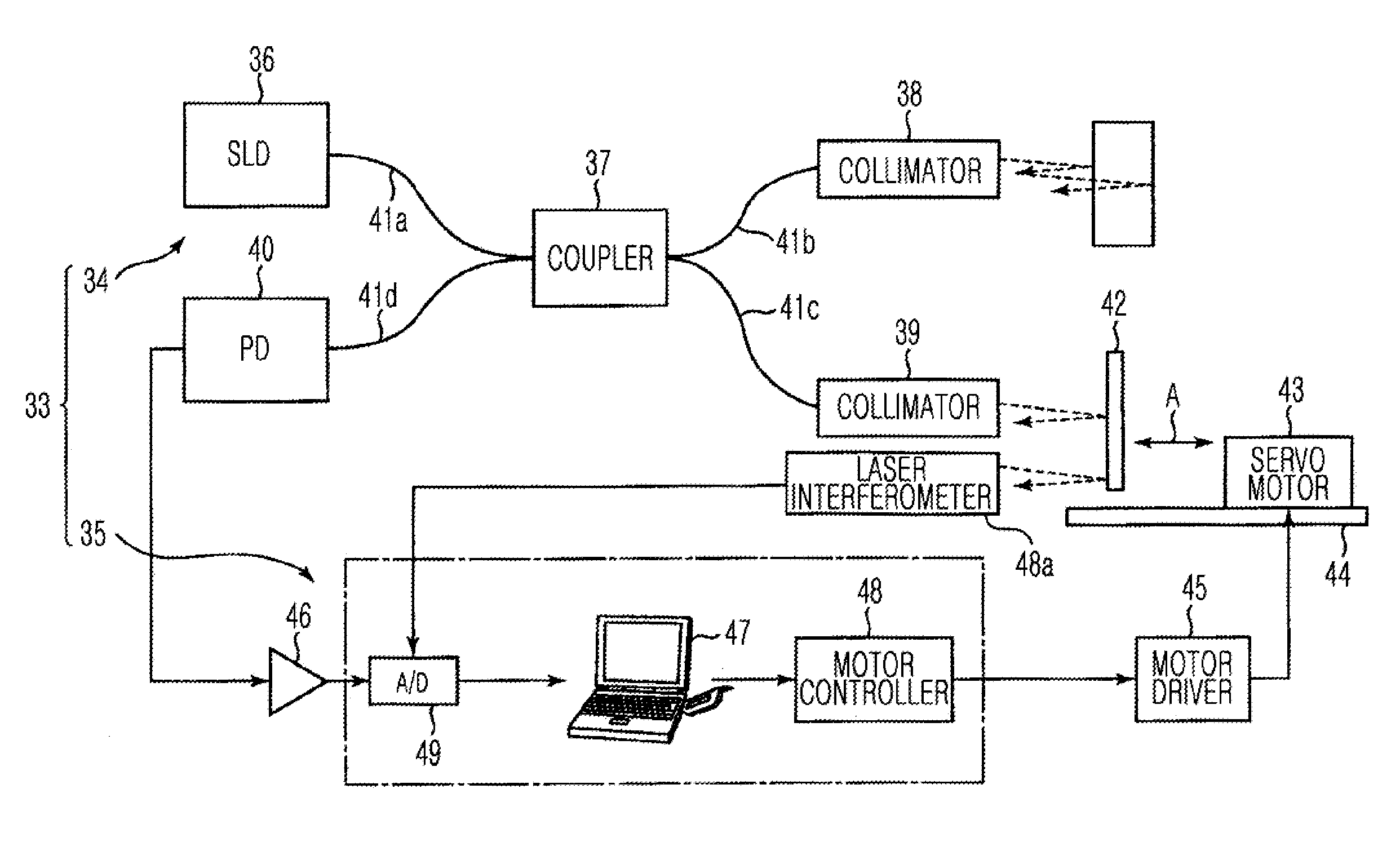
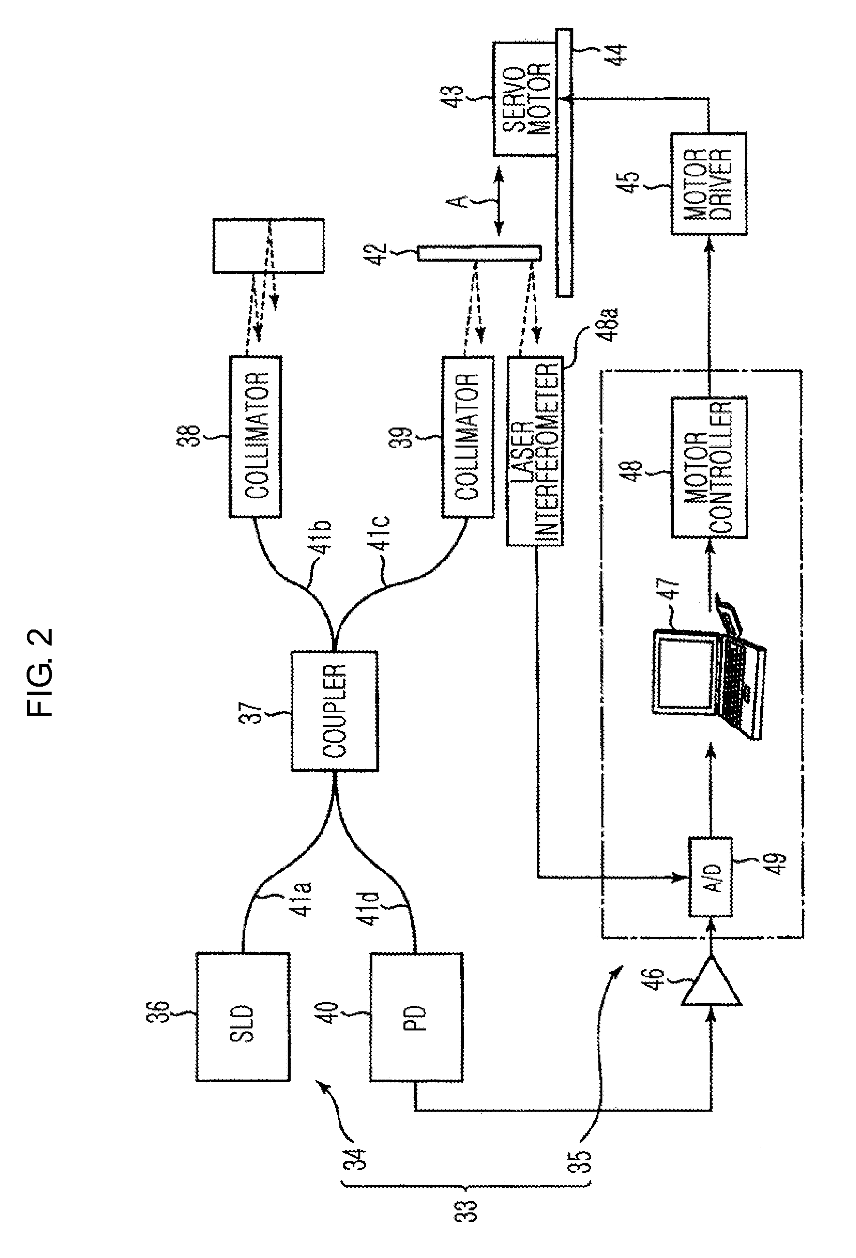
[0110]Like each embodiment described above, temperature measurement of the focus ring 85 having such a configuration is performed by irradiating a low-coherence light to the temperature measured member 85T from the collimator 38.

[0111]In the present embodiment, since the temperature measured member 85T is covered by the focus ring 85, a temperature of the focus ring 85 may be accurately measured with...


PUM

PropertyMeasurementUnit
Temperatureaaaaaaaaaa

Abstract

A component in a processing chamber of a substrate processing apparatus, where a temperature may be accurately measured by using a temperature measuring apparatus using an interference of a low-coherence light, even when a front surface and a rear surface are not parallel due to abrasion, or the like. A focus ring used in a vacuum atmosphere and of which a temperature is measured includes an abrasive surface exposed to an abrasive atmosphere according to plasma, a nonabrasive surface not exposed to the abrasive atmosphere, a thin-walled portion including a top surface and a bottom surface that are parallel to each other, and a coating member coating the top surface of the thin-walled portion, wherein a mirror-like finishing is performed on each of the top and bottom surfaces of the thin-walled portion.

Description

CROSS-REFERENCE TO RELATED PATENT APPLICATIONS[0001]This application claims the benefit of Japanese Patent Application No. 2011-069838 filed on Mar. 28, 2011, in the Japan Patent Office and U.S. patent Application Ser. No. 61 / 472,688 filed on Apr. 7, 2011, in the United States Patent Trademark Office, the disclosure of which are incorporated herein in their entireties by reference.BACKGROUND OF THE INVENTION[0002]1. Field of the Invention[0003]The present invention relates to a component in a processing chamber of a substrate processing apparatus, and a method of measuring a temperature of the component.[0004]2. Description of the Related Art[0005]In a substrate processing apparatus for performing a predetermined plasma process on a wafer constituting a substrate by using plasma generated in a processing chamber, members disposed in the processing chamber are worn away by the plasma. Specifically, an abrasion loss of a focus ring disposed to surround the wafer and formed of the same...

Claims


Application Information

Patent Timeline
IPC IPC(8): B32B3/14G01K11/00B32B18/00B05C11/00B32B33/00
CPCG01K5/48H01L21/67248Y10T428/24802Y10T428/24612Y10T428/192G01K11/14H01L21/3065H01L22/00
Inventor YAMAWAKU, JUNKOSHIMIZU, CHISHIOMATSUDO, TATSUO
Owner TOKYO ELECTRON LTD
Features
  • Generate Ideas
  • Intellectual Property
  • Life Sciences
  • Materials
  • Tech Scout
  • Unparalleled Data Quality
  • Higher Quality Content
  • 60% Fewer Hallucinations
Learn More