Therapeutic device and method for scar tissue therapy having intermediate and opposed heads

a technology of scar tissue and therapeutic device, which is applied in the field of massage therapy, can solve the problems of restricting the oxygen supply to muscles and connective tissues, affecting the healing effect of scar tissue, so as to maximize the therapeutic effect, reduce the risk of injury, and reduce the effect of scar tissue treatmen

Inactive Publication Date: 2012-10-04
STANBRIDGE STANLEY R
View PDF16 Cites 27 Cited by
  • Summary
  • Abstract
  • Description
  • Claims
  • Application Information

AI Technical Summary

Benefits of technology

[0021]The present invention provides an apparatus and method for effectively treating scar tissue within softer body tissue. The invention utilizes a novel massage apparatus having a reciprocating angular drive mechanism which is preferably handheld and which provides reciprocating arcuate power at an output coupling. The apparatus further includes a therapeutic device head having a generally T-shaped member which engages the output drive of the power source at the body portion of the T-center. The therapeutic device head further includes an elongated dual therapeutic device head which defines a generally larger planar massage surface and an opposed generally spherical smaller diameter portion. The therapeutic device head further includes a transversely positioned support flange upon which an intermediate head is supported. The intermediate massage head provides an alternative massage element for application to the skin and body of the patient. The head is oscillated through an arcuate movement at a predetermined frequency which has bee

Problems solved by technology

The repetitive stress often associated with such activities may cause muscles to tighten up and therein cause friction and inflammation between layers of moving body tissue.
When a muscle tightens up, swelling often occurs restricting the oxygen supply to the muscles and connective tissue.
Since there are no blood vessels that nourish this fibrotic tissue, it dries and constricts becoming dead, rigid and inflexible.
If the scar tissue and adhesions remain after their usefulness has expired, they often trap and contract around nerves causing pain and impairing movement.
While such scar tissue formation may be an important part of body response to trauma, inflammation and other stresses imposed upon the body, over time scar tissue can become a source of pain and difficulty.
All too frequently, scarring can lead to undesired and painful conditions which persist long after the healing response to

Method used


Image

  • Therapeutic device and method for scar tissue therapy having intermediate and opposed heads
  • Therapeutic device and method for scar tissue therapy having intermediate and opposed heads
  • Therapeutic device and method for scar tissue therapy having intermediate and opposed heads

Examples


Embodiment Construction

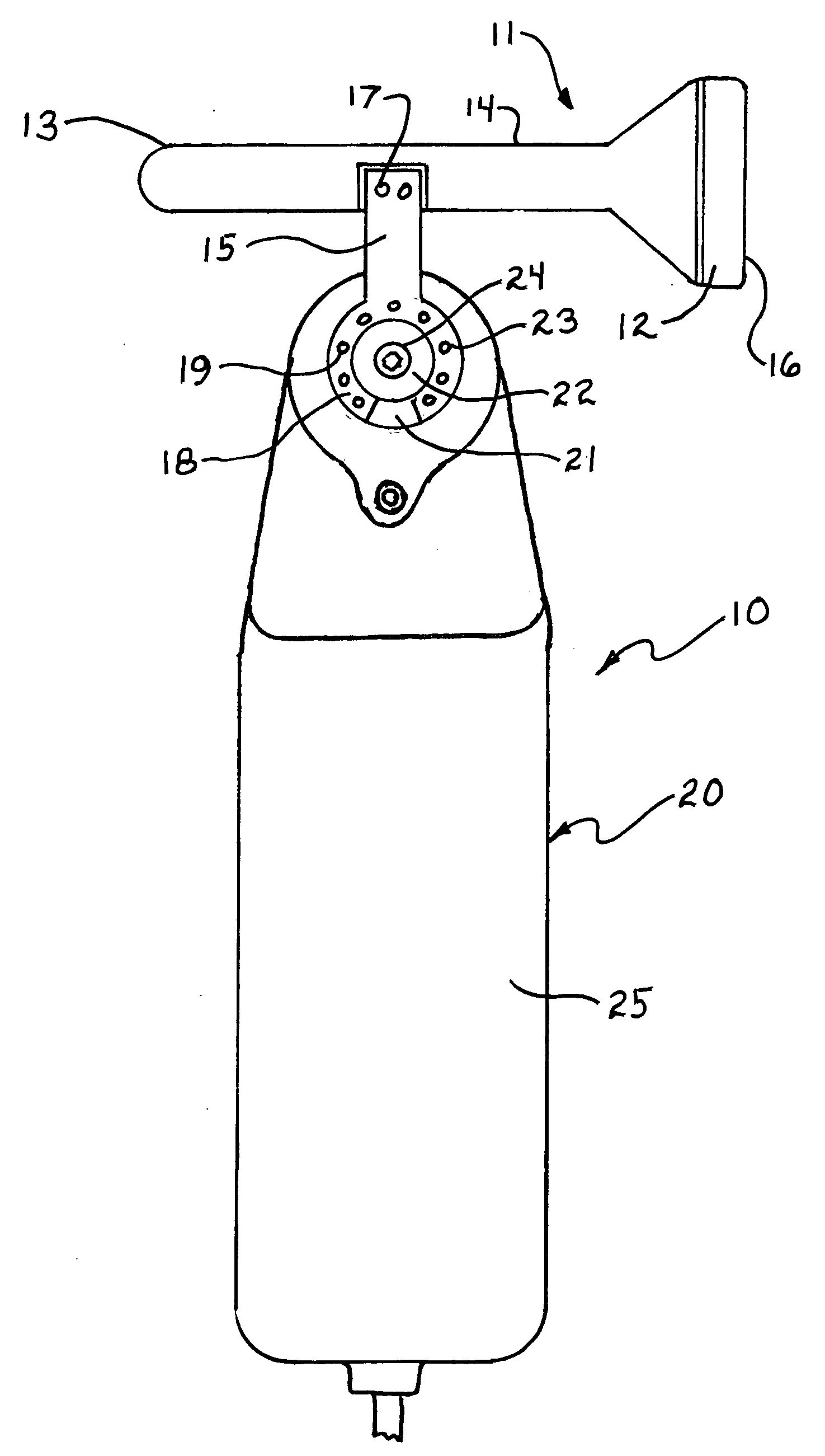
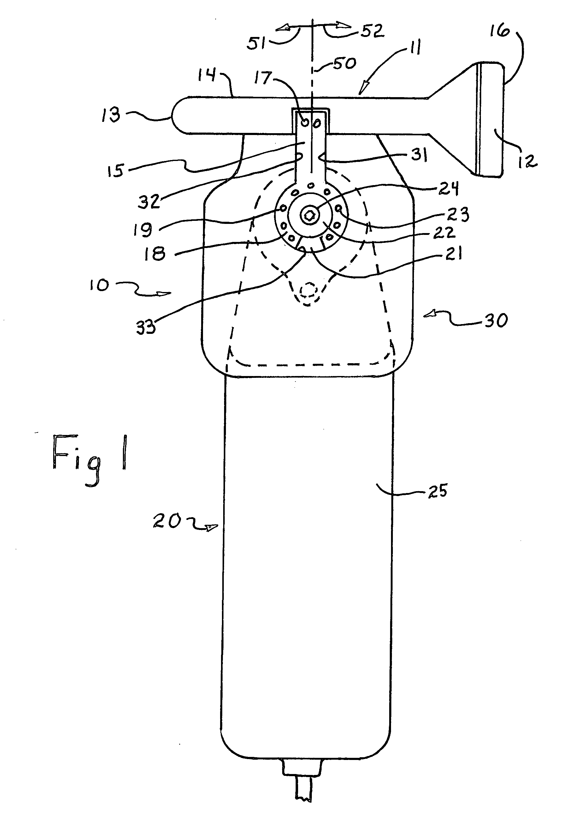
[0048]By way of overview, the present invention provides a novel tissue massage and method of tissue therapy which combine to effectively treat and for the most part remove troublesome scar tissue networks within softer body tissue. The therapeutic device utilizes a power unit which provides arcuate oscillatory motion of an output shaft of the type typically used for handheld detail work saw apparatus. The therapeutic device further utilizes a novel therapeutic device head defining a center member which is operatively coupled to the power unit output shaft and which further includes a pair of opposed therapeutic device heads. In the preferred fabrication of the invention, the opposed heads of the therapeutic device head include a generally planar larger diameter therapeutic device head and a smaller diameter generally spherically shaped massaged head. In accordance with the inventive method, the power unit is energized causing the therapeutic device head to rapidly oscillate through...


PUM


Abstract

A therapeutic device includes a power unit for cyclically moving a therapeutic head unit at a frequency selected to cause compression wave energy to propagate through body tissue to a target scar tissue structure. The therapeutic head unit includes a plurality of differently shaped therapeutic heads to be pressed against the body surface.

Description

CROSS-REFERENCE TO RELATED APPLICATION[0001]This application claims the benefit of and priority under 35 U.S.C. 119(e) of U.S. Provisional Patent Application No. 61 / 459,620 entitled THERAPEUTIC DEVICE AND METHOD FOR SCAR TISSUE THERAPY filed Dec. 16, 2010 in the name of Stanley Stanbridge and Provisional Patent Application No. 61 / 520,347 entitled THERAPEUTIC DEVICE AND METHOD FOR SCAR TISSUE THERAPY HAVING INTERMEDIATE AND OPPOSED HEADS filed Jun. 7, 2011 in the name of Stanley Stanbridge, the disclosure of which are incorporated herein by reference.FIELD OF THE INVENTION[0002]This invention relates generally to massage therapy and particularly to apparatus and treatment methods for dealing with scar tissue conditions together with various conditions such as tissue inflammation, carpal tunnel syndrome, tendonosis, muscle spasms, trapped nerves, motion range limitations, contractures, neuromas, adhesions, knee problems, tennis elbow, headaches, TMJ, and gout as well as back, shoulder...

Claims


Application Information

Patent Timeline
IPC IPC(8): A61H7/00
CPCA61H2201/0153A61H2201/0169A61H23/008A61H23/0218A61H23/0254A61H23/006A61H2201/0165A61H2201/1215A61H2201/1436A61H2201/149A61H2201/0157
Inventor STANBRIDGE, STANLEY R.
Owner STANBRIDGE STANLEY R
Why Eureka
Try Eureka