Drive shaft for a surgical reamer

a technology of surgical reamer and drive shaft, which is applied in the field of drive shaft for surgical reamer, can solve the problems of more costly and fragile than the conventional drive shaft, the device is however costly and must be re-used, and the cleaning and sterilization is difficult, so as to achieve the effect of light and less expensive, avoiding the difficulties and costs of sterilization, and facilitating the insertion and withdrawal of the tool

Inactive Publication Date: 2012-10-04
CHIRMAT
View PDF14 Cites 31 Cited by
  • Summary
  • Abstract
  • Description
  • Claims
  • Application Information

AI Technical Summary

Benefits of technology

[0012]This solution notably has the advantage that the drive shaft thus obtained is lighter and less expensive than the drive shafts of the prior art and can be used a single time and destroyed after use, thus avoiding the difficulties and the costs of sterilizing associated with the use of the known drive shafts.
[0013]This solution also makes it possible to achieve a flexible shaft with a metallic connection element at its extremity and a constant transverse section along the rod and the connection element, thus also making easier the insertion and withdrawal of the tool. This shaft is hollow to allow a Kirschner rod as reference to pass.

Problems solved by technology

These devices are however costly and must be re-used.
They are however difficult to clean and to sterilize, especially in a hospital environment.
Though these shafts are easier to clean and sterilize, they are however more costly and fragile than the conventional drive shafts.
The device of this application is not designed for reaming a bone, the aim being to increase the rigidity of the device and ream or bore holes at high speed without creating vibration effects.
This device is not made of glass fiber and has a complicated distal coupling system.

Method used


Image

  • Drive shaft for a surgical reamer
  • Drive shaft for a surgical reamer
  • Drive shaft for a surgical reamer

Examples


Embodiment Construction

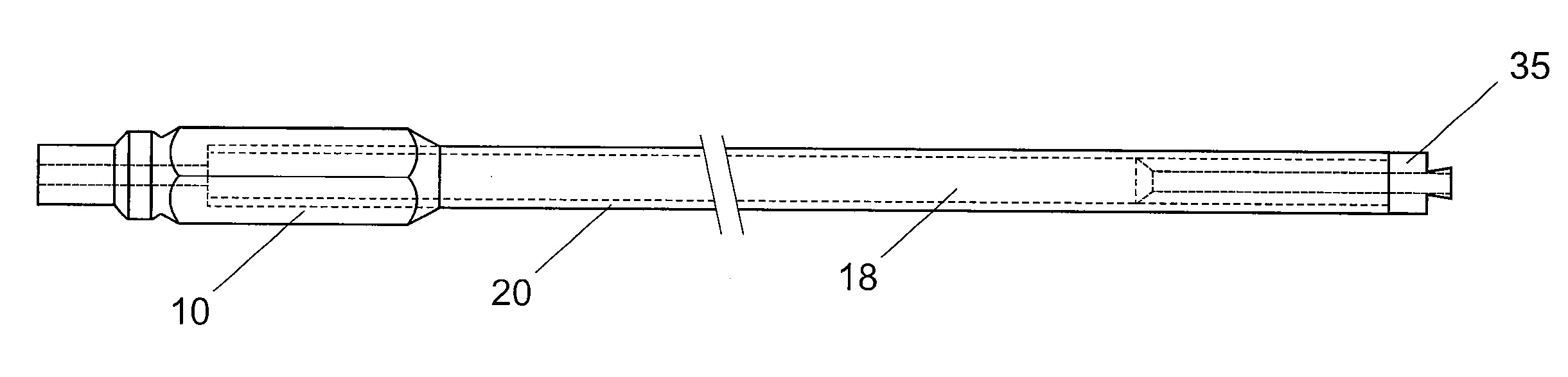
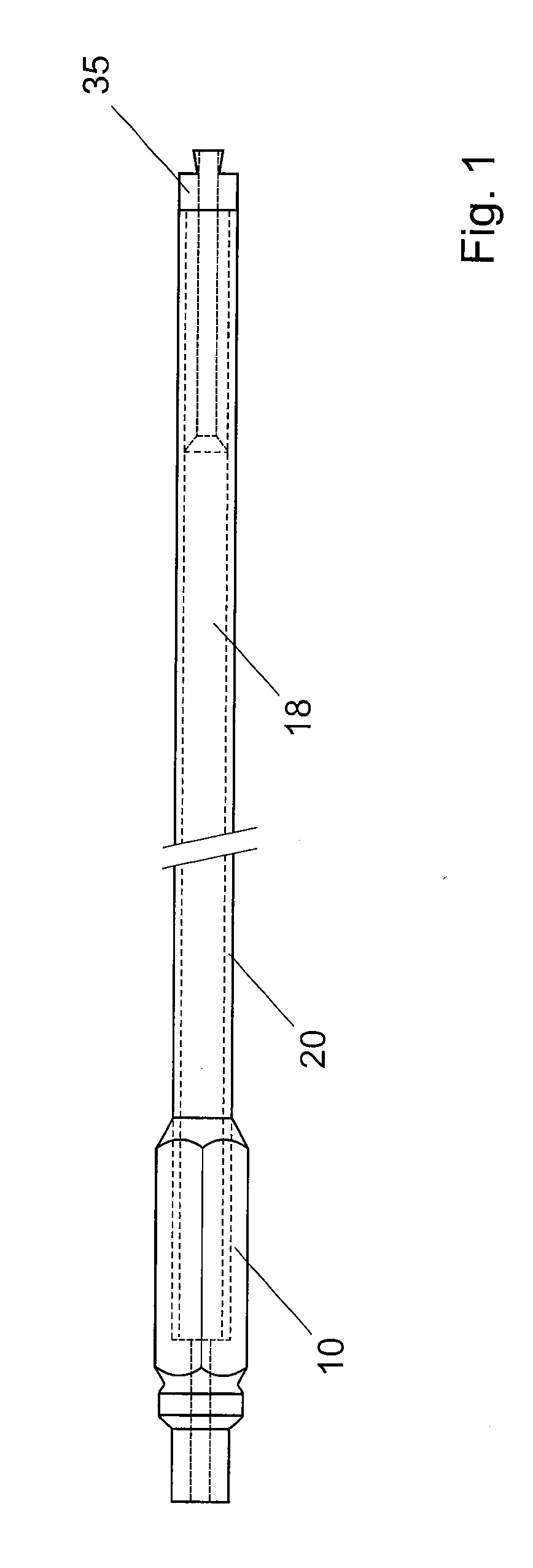
[0019]With reference to FIG. 1, according to one embodiment, the transmission shaft of the invention comprises a flexible rod 20 of composite material, for example with a fiber-reinforced plastic matrix. The length of the rod is adapted to that of the medullary canal of the bone on which one wishes to operate. In a preferred embodiment, this length is greater than 70 cm, for example 1m, which advantageously makes it possible to perform arthrodesis in a single step. Known metallic transmission shafts with a wound coil have a length of approximately 50 cm and they thus do not allow arthrodesis to be performed in a single step. Furthermore, there are difficulties in making a known metallic transmission shaft with a length lower than 1 m, obtained by cutting a shaft of greater length, because of the spring's helix structure.

[0020]In a preferred embodiment, the inventive shaft is manufactured having a length of 1 m. As it is made of composite material, it is possible to cut it into two e...


PUM

PropertyMeasurementUnit
transverse diameteraaaaaaaaaa
lengthaaaaaaaaaa
lengthaaaaaaaaaa

Abstract

Drive shaft for interchangeable reaming heads intended for surgical use, in particular a reaming head used prior to the positioning of an intramedullary nail in the femur or in a long bone. The shaft has a rod (20) made from composite material, e.g. carbon and/or glass fiber reinforced polymer, and a connection element (35) for the coupling of an interchangeable reaming head. One portion (32) of said connection element (35) is inserted into a cavity in the first end (21) of said rod (20). The inventive shaft has a constant diameter, a smooth external surface and a low cost such that it can be disposed of after use.

Description

[0001]This application is a continuation of PCT / EP2010 / 066120, filed Oct. 26, 2010, which claims priority to 2009CH-10657, filed Oct. 28, 2009, the entire contents of which are hereby incorporated by reference.TECHNICAL FIELD[0002]The present invention concerns a drive shaft for a surgical reamer, in particular a drive shaft with a structure made from composite material reinforced with long and / or short fibers, for driving an interchangeable reaming head for reaming or boring the intramedullary canal or cavity.STATE OF THE ART[0003]Centromedullary nailing is one of the most widely used therapeutic techniques in the treatment of fractures and in the reconstitution of long bones, for example and in a non limiting fashion the femur, but also the tibia or the humerus. According to this method, the medullary canal is widened to the desired diameter by means of several interchangeable reaming heads of different diameter mounted successively on a flexible drive shaft capable of following t...

Claims


Application Information

Patent Timeline
Patent Type & Authority Applications(United States)
IPC IPC(8): A61B17/56
CPCA61B17/1631Y10T408/665A61F2/30965A61B2017/00831
Inventor ARLETTAZ, YVANBONJOUR, CHRISTIAN
Owner CHIRMAT
Why Eureka
Try Eureka