Delay lock loop with a charge pump, loop filter, and method of phase locking of a delay lock loop

a delay lock and charge pump technology, applied in the direction of electrical equipment, pulse automatic control, etc., can solve the problem of large power consumption, and achieve the effect of reducing power consumption, shortening locking time, and reducing jitter

Active Publication Date: 2012-10-11
ETRON TECH INC
View PDF3 Cites 9 Cited by
  • Summary
  • Abstract
  • Description
  • Claims
  • Application Information

AI Technical Summary

Benefits of technology

[0012]The present invention provides a delay lock loop, a loop filter, and a method of phase locking of a delay lock loop. The delay lock loop, the loop filter, and the method utilize a first switch and a second switch of a loop filter to change capacitor values when the loop filter is in phase tracking and phase locking. Therefore, when the loop filter is in the phase tracking, the loop filter only utilizes a voltage of a smaller capacitor (a first capacitor) to control a voltage control delay line for locking fast; and when the loop filter is in the phase locking, the loop filter utilizes a voltage of a larger capacitor (the first capacitor and a second capacitor in parallel) to control the voltage control delay line. Therefore, the present invention has shorter locking time, lower power consumption, lower jitter, and no phase shift caused by mismatched switch currents, and can enter the power down mode for a long time.

Problems solved by technology

However, the delay lock loop 100 with the capacitor C with the large capacitance has a problem of large power consumption due to the large charging / discharging currents.

Method used


Image

  • Delay lock loop with a charge pump, loop filter, and method of phase locking of a delay lock loop
  • Delay lock loop with a charge pump, loop filter, and method of phase locking of a delay lock loop
  • Delay lock loop with a charge pump, loop filter, and method of phase locking of a delay lock loop

Examples


Embodiment Construction

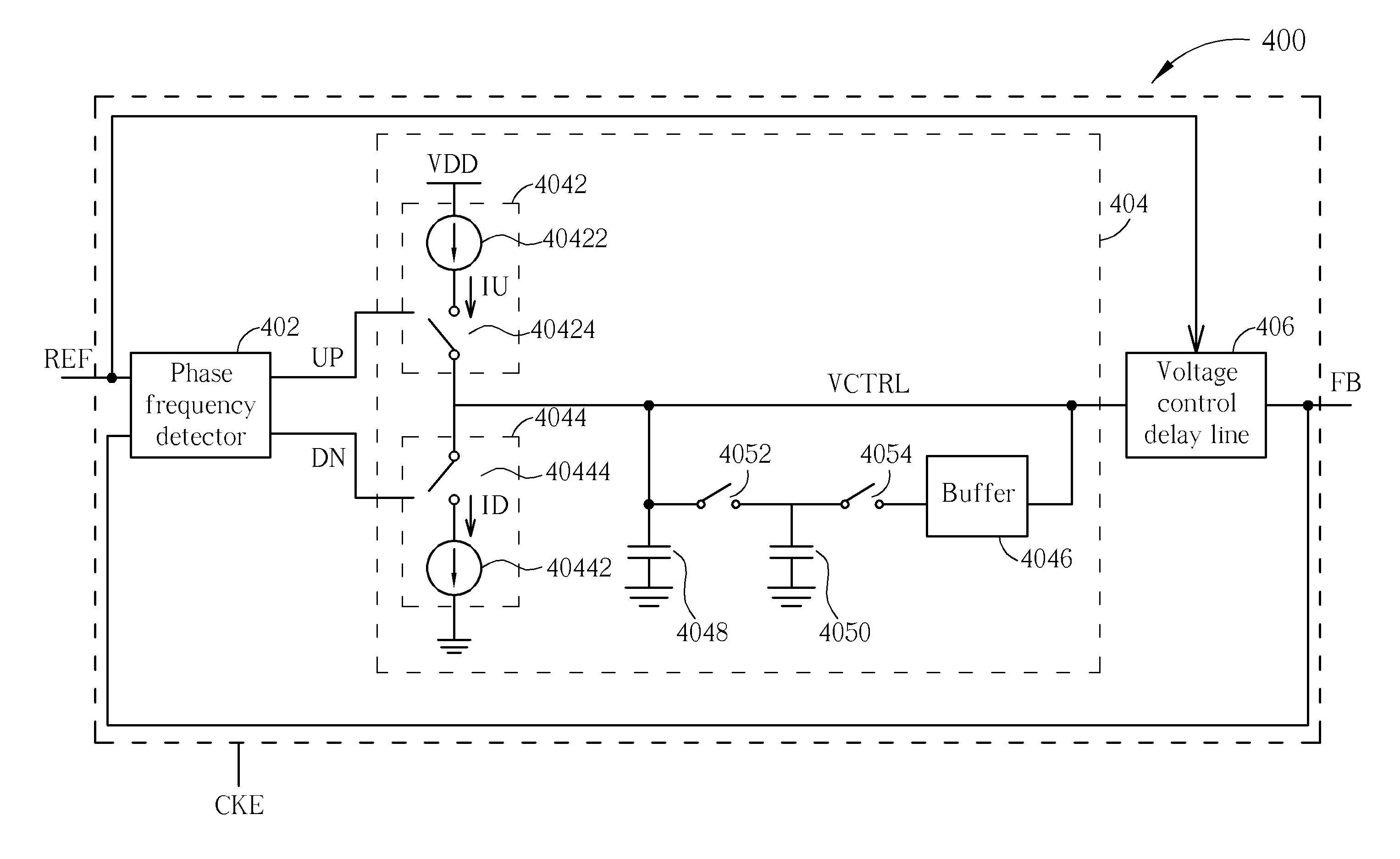
[0023]Please refer to FIG. 4. FIG. 4 is a diagram illustrating a delay lock loop 400 according to an embodiment. The delay lock loop 400 includes a phase frequency detector 402, a loop filter 404, and a voltage control delay line 406. The phase frequency detector 402 has a first input terminal for receiving a reference clock REF, a second input terminal for receiving a feedback clock FB, a first output terminal for outputting an upper switch signal UP, and a second output terminal for outputting a lower switch signal DN, where when a phase of the feedback clock FB leads a phase of the reference clock REF, the upper switch signal UP is at a logic-low voltage and the lower switch signal DN is at a logic-high voltage; and when the phase of the feedback clock FB lags the phase of the reference clock REF, the upper switch signal UP is at the logic-high voltage and the lower switch signal DN is at the logic-low voltage. But, when the phase of the feedback clock FB leads the phase of the r...


PUM


Abstract

A delay lock loop includes a phase frequency detector, a loop filter, and a voltage controlled delay circuit. The phase frequency detector is used for outputting an upper switch signal or a lower switch signal according to a reference clock and a feedback clock. The loop filter includes a first capacitor, a second capacitor, and a first switch. The first capacitor is charged or discharged and the first switch is turned off during a phase tracking period. The first capacitor and the second capacitor are charged or discharged and the first switch is turned on during a phase locking period. The voltage controlled delay circuit is used for outputting the feedback clock according to the reference clock and a control voltage outputted by the loop filter.

Description

BACKGROUND OF THE INVENTION[0001]1. Field of the Invention[0002]The present invention is related to a delay lock loop, a loop filter, and a method of phase locking of a delay lock loop, and particularly to a delay lock loop that has a switched capacitor loop filter, a loop filter that has a switched capacitor, and a method of phase locking of a delay lock loop that has a switched capacitor loop filter.[0003]2. Description of the Prior Art[0004]Please refer to FIG. 1. FIG. 1 is a diagram illustrating a delay lock loop 100 according to the prior art. The delay lock loop 100 includes a phase frequency detector 102, a charge pump 104, a voltage control delay line 106, and a capacitor C. The phase frequency detector 102 is used for receiving a reference clock REF and a feedback clock FB, and outputting an upper switch signal UP or a lower switch signal DN according to the reference clock REF and the feedback clock FB. The charge pump 104 is used for charging or discharging according to t...

Claims


Application Information

Patent Timeline
Patent Type & Authority Applications(United States)
IPC IPC(8): H03L7/08
CPCH03L7/08H03L7/1075H03L7/093H03L7/0816
Inventor TENG, KUANG-FU
Owner ETRON TECH INC
Why Eureka
Try Eureka