Center hole machining method for shaft blank and center hole machining apparatus

a center hole machining and shaft blank technology, applied in the direction of total factory control, programme control, electric programme control, etc., can solve the problems of not addressing at all the reduction of the machining allowance of the shaft blank for reducing material cost, the shaft blank cannot be finished in a shape that meets design values, and the entire thickness of the shaft blank, etc., to achieve the effect of reducing the material cos

Active Publication Date: 2012-10-11
KOMATSU NTC LTD
View PDF6 Cites 10 Cited by
  • Summary
  • Abstract
  • Description
  • Claims
  • Application Information

AI Technical Summary

Benefits of technology

[0033]According to the present invention as described above, it is possible to appropriately set a position of a center hole and prevent a blank surface from remaining on a shaft blank after machining even when the machining allowance of the shaft blank is set to be small. Therefore, material cost can be reduced.

Problems solved by technology

However, the aforementioned well-known arts do not address at all reduction in machining allowance of the shaft blank for reducing material cost.
This is due to defect, misalignment, deformation and etc. of the molds.
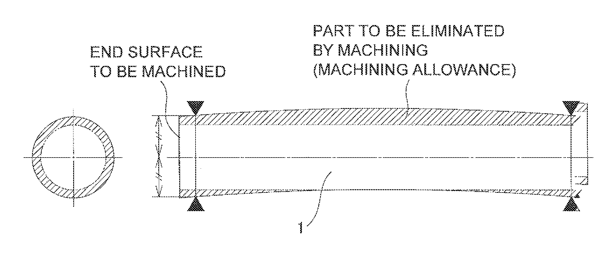
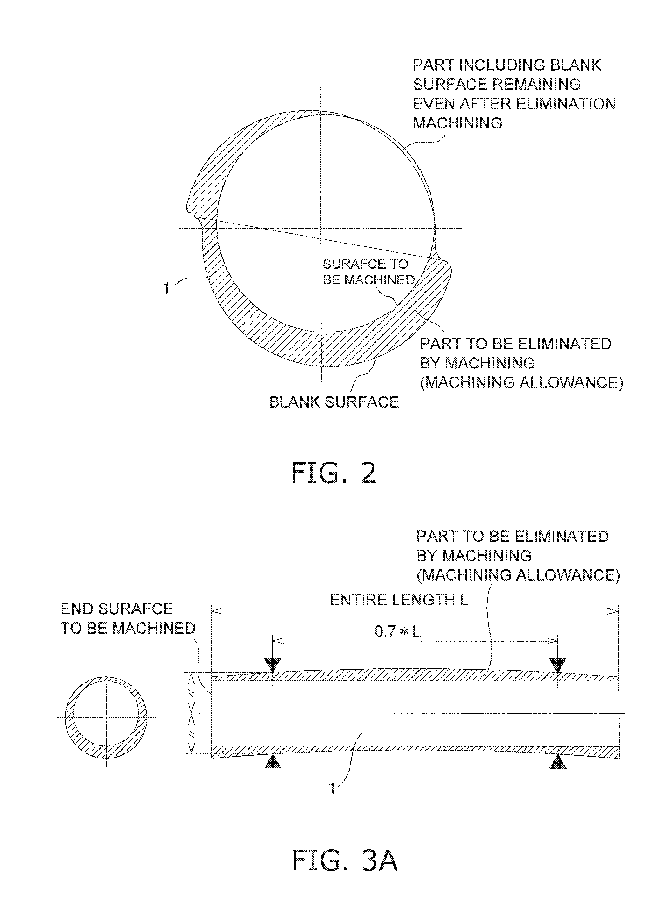
In practical situations, however, the shaft blank cannot be necessarily finished in a shape satisfying design values due to the following factors such as deficit of forging / casting molds in fabricating the shaft blank.
(1) The top and bottom molds are separated away from each other due to the excessive amount of material and this results in an entirely thick shaft blank.
(2) The top and bottom molds are misaligned and this results in a shaft blank with a horizontally misaligned shape.
(3) The top and bottom molds are slanted from each other and a shaft blank having a non-uniform thickness is thereby produced.
In this case, however, the shaft blank tends to be wobbled in milling the both end surfaces thereof due to relatively long distance set from the end surfaces of the shaft blank to be actually milled to the camped positions thereof.
In such a method, however, it is required to uselessly machine shaft blanks for grasping tendency of shape misalignment of shaft blanks every time another lot becomes a machining target and tendency of shape misalignment of the shaft blanks varies.

Method used


Image

  • Center hole machining method for shaft blank and center hole machining apparatus
  • Center hole machining method for shaft blank and center hole machining apparatus
  • Center hole machining method for shaft blank and center hole machining apparatus

Examples


first exemplary embodiment

1. First Exemplary Embodiment

Crankshaft Machining System

[0053]FIG. 4 illustrates a shaft machining system including a center hole machining machine 10 according to an exemplary embodiment of the present invention. The shaft machining system 100 includes the center hole machining machine 10, a computer 20 and a machining machine 30. The center hole machining machine 10 is configured to bore a center hole in each of the both end surfaces of a shaft blank. The computer 20 is configured to execute a processing for determining the position of a center hole to be bored in each of the both end surfaces of the shaft blank. The machining machine 30 is configured to execute a predetermined working for the shaft blank after the center holes are bored in the shaft blank.

[0054]The center hole machining machine 10 includes a shape meter 11, which is an example of a shape data obtaining unit configured to measure the shape of a shaft blank.

[0055]The shape meter 11 includes, for instance, either a ...

example

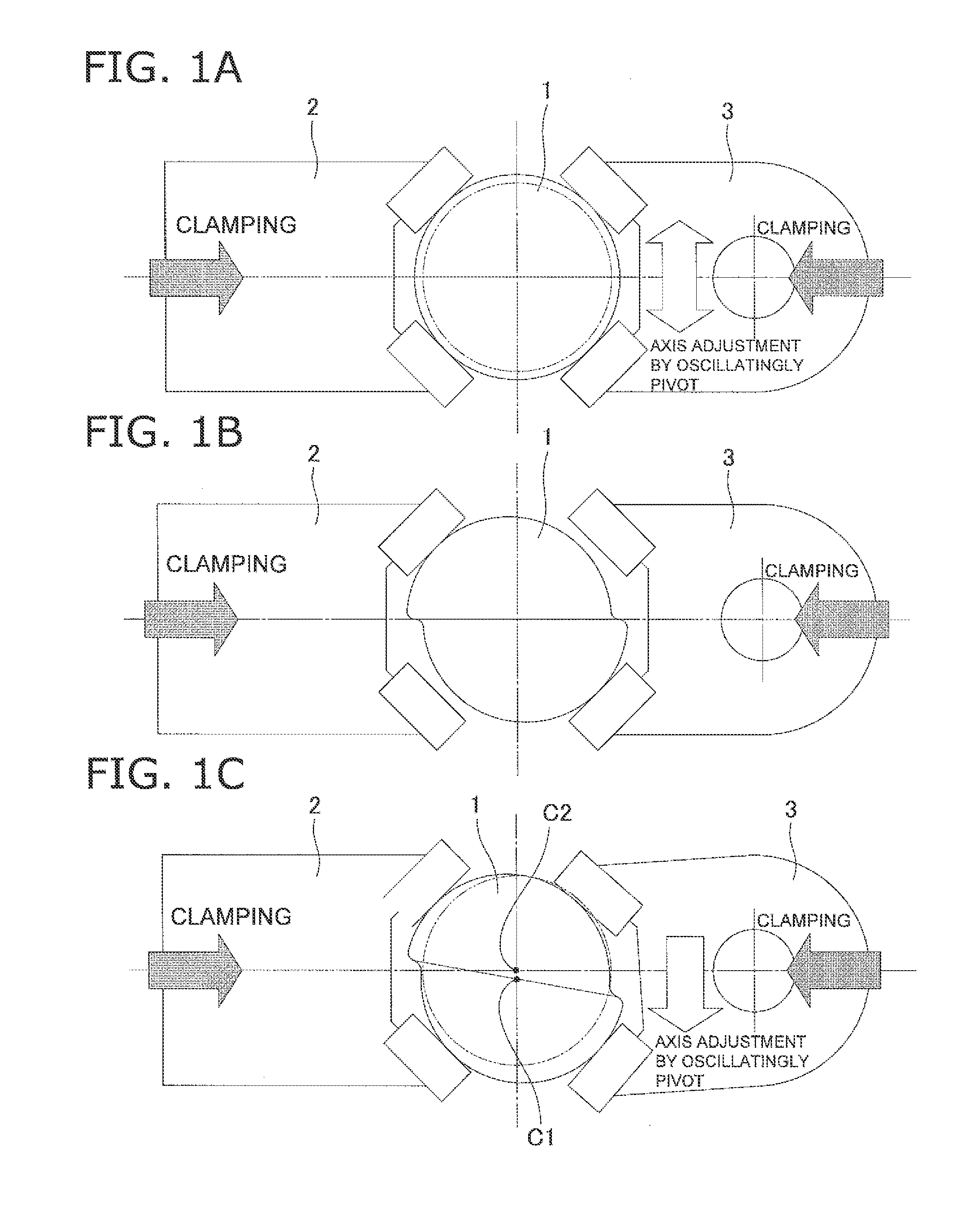
[0085]Shifting of a center axis will be specifically explained with reference to FIGS. 9A and 9B. It should be noted that FIG. 9A illustrates a case that machining allowance is insufficient in one position whereas FIG. 9B illustrates a case that machining allowance is insufficient in a plurality of positions.

[0086]As illustrated in a diagram (a) of FIG. 9A, when machining allowance is either “zero” or “minus” in one position (FIG. 9 exemplifies a case of “minus” machining allowance), the center axis is shifted on a straight line connecting the center axis and the prospective machining portion towards the opposite side of the position where machining allowance is insufficient, so that the same amount of machining allowance can be produced on the both radial sides as illustrated in a diagram (b) of FIG. 9A. When machining allowance becomes insufficient in another position after the shifting of the center axis as illustrated in a diagram (c) of FIG. 9A, the aforementioned processing is...

second exemplary embodiment

2. Second Exemplary Embodiment

[0089]The aforementioned exemplary embodiment has exemplified the case that the shaft blank is formed in a cylindrical shape. However, the present invention can be similarly applied to such a case that a cam shaft 40 is machined as illustrated in FIG. 10. In this case, the cam shaft 40 includes cylindrical journal portions 41a to 41e and cam portions 42a to 42d. Similarly to the aforementioned exemplary embodiment, the least-square method for a true circle is herein applied to the journal portions 41a to 41e. On the other hand, best-fitting based on the least-square method is applied to the design values of the cam shapes of the cam portions 42a to 42d. Further, as to the cam shapes, relative angles are preliminarily set among the respective cam portions. Therefore, a center axis is calculated by incorporating the relative angles into best-fit calculation.


PUM


Abstract

A center hole machining method includes first to fifth steps. The first step includes obtaining outer peripheral shape data of a plurality of portions of the shaft blank in an axial direction. The second step includes obtaining a center axis by comparing measured data of the portions of the shaft blank with design data. The third step includes calculating a minimum distance from the center axis to the outer periphery in each of the portions of the shaft blank. The fourth step includes shifting the center axis in a direction of making the minimum distance greater than the machining dimension and repeatedly executing the third step when the minimum distance is less than or equal to the machining dimension. The fifth step includes boring the center hole in an end surface of the shaft blank at a position arranged on a line extended from the center axis.

Description

CROSS-REFERENCE TO RELATED APPLICATIONS[0001]This application claims priority to Japanese Patent Application No. 2010-016254 filed on Jan. 28, 2010, the disclosure of which is hereby incorporated herein by reference in its entirety.TECHNICAL FIELD[0002]The present invention relates to a center hole machining method, particularly to a center hole machining method for boring a center hole in a shaft blank formed by means of forging or casting in machining the outer periphery of the shaft blank. Further, the present invention relates to a center hole machining apparatus using the center hole machining method.BACKGROUND ART[0003]For example, shaft blanks such as for a camshaft embedded in an engine are mainly formed by means for forging. In such a shaft blank, cutting and polishing processes are executed for the outer peripheral surfaces of cam portions and journal portions.[0004]As a process preceding the aforementioned processes for the shaft blank, it is required to bore center holes...

Claims


Application Information

Patent Timeline
Patent Type & Authority Applications(United States)
IPC IPC(8): G05B19/19
CPCB23B49/04B23B2215/16B23Q17/20G05B2219/49113G05B19/402G05B2219/45148B23Q17/2233Y02P90/02
Inventor YOSHIMOTO, AKIHIRO
Owner KOMATSU NTC LTD
Why Eureka
Try Eureka