Method for Igniting a Fuel-Air Mixture of a Combustion Chamber, Particularly in an Internal Combustion Engine by Generating a Corona Discharge

Inactive Publication Date: 2012-10-18
BORGWARNER BERU SYST
View PDF5 Cites 20 Cited by
  • Summary
  • Abstract
  • Description
  • Claims
  • Application Information

AI Technical Summary

Benefits of technology

[0007]The present invention relates to a method for igniting a fuel-air mixture in one or more combustion chambers by means of corona dis

Problems solved by technology

This method has the disadvantage that the formation of the corona is not optimal and in particular does not always reach an optimal size of the corona.
The disadvantage with the procedure known from WO 2010/011838 A1 is that it is not possible to ignite the fuel-air mixture by a corona discharge without generating spark discharges f

Method used


Image

  • Method for Igniting a Fuel-Air Mixture of a Combustion Chamber, Particularly in an Internal Combustion Engine by Generating a Corona Discharge
  • Method for Igniting a Fuel-Air Mixture of a Combustion Chamber, Particularly in an Internal Combustion Engine by Generating a Corona Discharge
  • Method for Igniting a Fuel-Air Mixture of a Combustion Chamber, Particularly in an Internal Combustion Engine by Generating a Corona Discharge

Examples


Embodiment Construction

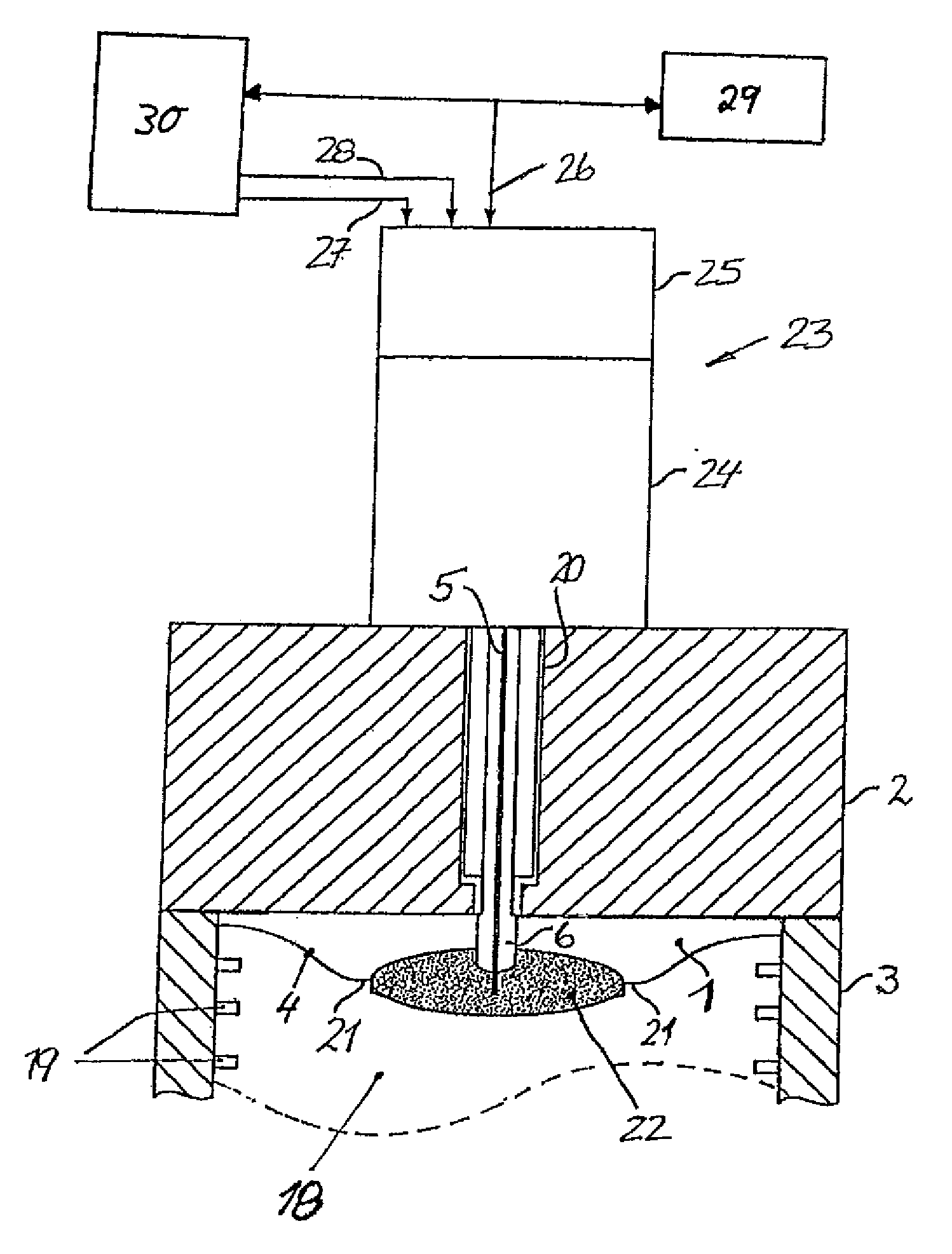
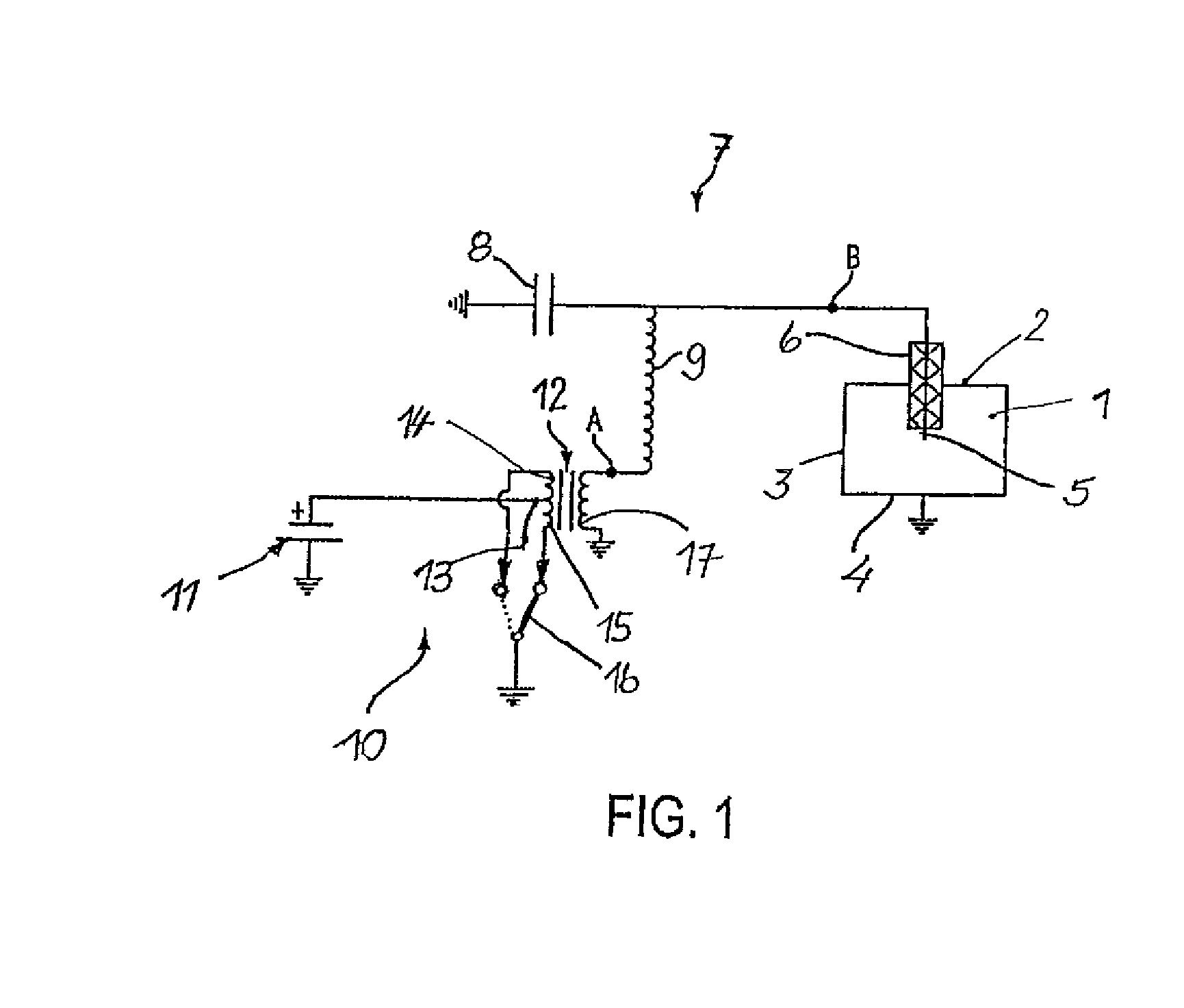
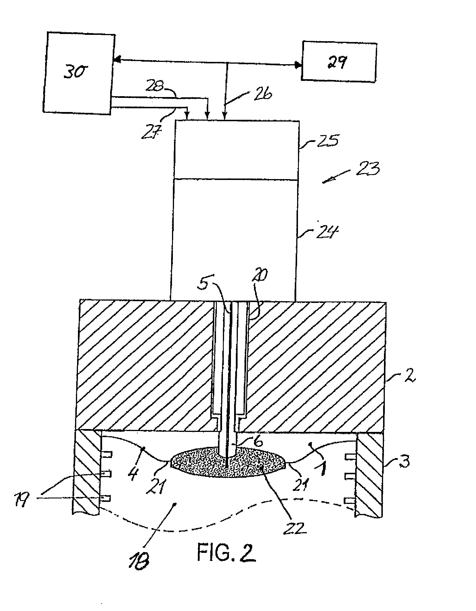
[0033]FIG. 1 shows a combustion chamber 1, which is delimited by grounded walls 2, 3 and 4. From above, an ignition electrode 5 projects into the combustion chamber 1, the electrode being surrounded over part of the length thereof by an insulator 6, by which it is guided in an electrically insulated manner through the upper wall 2 into the combustion chamber 1. The ignition electrode 5 and the walls 2 to 4 of the combustion chamber 1 form part of a series oscillating circuit 7, which also comprises a capacitor 8 and an inductor 9. The series oscillating circuit 7 can, of course, comprise further inductors and / or capacitors and other elements, which a person skilled in the art will be familiar with as possible components of series oscillating circuits.

[0034]A high frequency generator 10 is provided for exciting the oscillating circuit 7, the generator having a direct current source 11 and a transformer 12 with a center tap 13 on the primary side, with two primary windings 14 and 15 m...


PUM


Abstract

The invention relates to a method for igniting a fuel-air mixture in an internal combustion engine. An electric transformer excites an oscillating circuit connected to a secondary winding of the transformer. A capacitor is formed by an ignition electrode together with the wall of a combustion chamber through which it extends. The excitation of the oscillating circuit is controlled by generating a corona discharge igniting the fuel-air mixture. Before each ignition time the voltage applied to a primary winding of the transformer is incrementally increased, and the intensity of the current flowing in the primary winding is measured repeatedly at the same primary voltage. The variation of the values of the related primary current is determined, and the incremental increase in the primary voltage is aborted at a value thereof at which the variation of the primary current intensity reaches or exceeds a predetermined limit.

Description

[0001]WO 2004 / 063560 A1 discloses how a fuel-air mixture in a combustion chamber of an internal combustion engine can be ignited by a corona discharge generated in the combustion chamber. For this purpose, an ignition electrode extends in an electrically insulated manner through one of the grounded walls of the combustion chamber and projects into the combustion chamber, preferably opposite of a reciprocating piston provided in the combustion chamber. Together with the grounded walls of the combustion chamber as the counter-electrode, the ignition electrode forms a capacitor. The combustion chamber with the content thereof acts as a dielectric. Depending on the cycle of the piston, it contains air, or a fuel-air mixture, or exhaust gas.[0002]The capacitor forms part of an electric oscillating circuit, which is excited using a high frequency AC voltage that is generated by means of a center-tapped transformer. The transformer cooperates with a control unit, which applies a predetermi...

Claims


Application Information

Patent Timeline
IPC IPC(8): F02P3/06
CPCF02P3/06F02P13/00F02P23/04F02P17/12F02P3/01
Inventor SCHREMMER, TORSTEN
Owner BORGWARNER BERU SYST
Why Eureka
Try Eureka