Acoustic cleaning assembly for use in power generation systems and method of assembling same

a technology for power generation systems and cleaning assemblies, applied in the direction of cleaning using liquids, instruments, separation processes, etc., can solve the problems of excessive outage time, inconvenient cleaning, and inability to clean, so as to facilitate the generation of sound waves, facilitate the removal of debris, and facilitate the effect of sound waves

Active Publication Date: 2012-10-25
PARKER INTANGIBLES LLC
View PDF1 Cites 1 Cited by
  • Summary
  • Abstract
  • Description
  • Claims
  • Application Information

AI Technical Summary

Benefits of technology

[0005]In one aspect, an acoustic cleaning assembly is provided. The acoustic cleaning assembly includes a horn assembly and a generator body that is coupled to the horn assembly. The generator body includes an inner surface that at least partially defines an outlet plenum, and an opening that extends in flow communication between the horn assembly and the outlet plenum. An end cap is coupled to the generator body and includes an inner surface that at least partially defines an inlet plenum. A diaphragm is coupled between the generator body and the end cap. The diaphragm channels air from the inlet plenum to the outlet plenum to facilitate generating sound waves within the outlet plenum.
[0006]In another aspect, a power generation system is provided. The power generation system includes a combustion assembly for generating combustion gases and a particulate filter assembly that is coupled to the combustion assembly for removing particulate from the combustion gases. At least one acoustic cleaning assembly is coupled to the particulate filter assembly to facilitate removing debris from the particulate filter assembly. The acoustic cleaning assembly includes a horn assembly and a generator body that is coupled to the horn assembly. The generator body includes an inner surface that at least partially defines an outlet plenum, and an opening that extends in flow communication between the horn assembly and the outlet plenum. An end cap is coupled to the generator body and includes an inner surface that at least partially defines an inlet plenum. A diaphragm is coupled between the generator body and the end cap. The diaphragm channels air from the inlet plenum to the outlet plenum to facilitate generating sound waves within the outlet plenum.

Problems solved by technology

The formation of such deposits in air treatment systems may adversely affect the operation of the components.
For example, buildup on a surface of these components may cause treatment inefficiencies, pressure drops, and excessive outage time.
Generally, known methods, including soot blowing, may cause erosion to surfaces being cleaned.
However, the loss of pressurized air through the relief valve increases the cost of operating the acoustic cleaner by increasing an amount of pressurized air required to operate the acoustic cleaner.

Method used


Image

  • Acoustic cleaning assembly for use in power generation systems and method of assembling same
  • Acoustic cleaning assembly for use in power generation systems and method of assembling same
  • Acoustic cleaning assembly for use in power generation systems and method of assembling same

Examples


Embodiment Construction

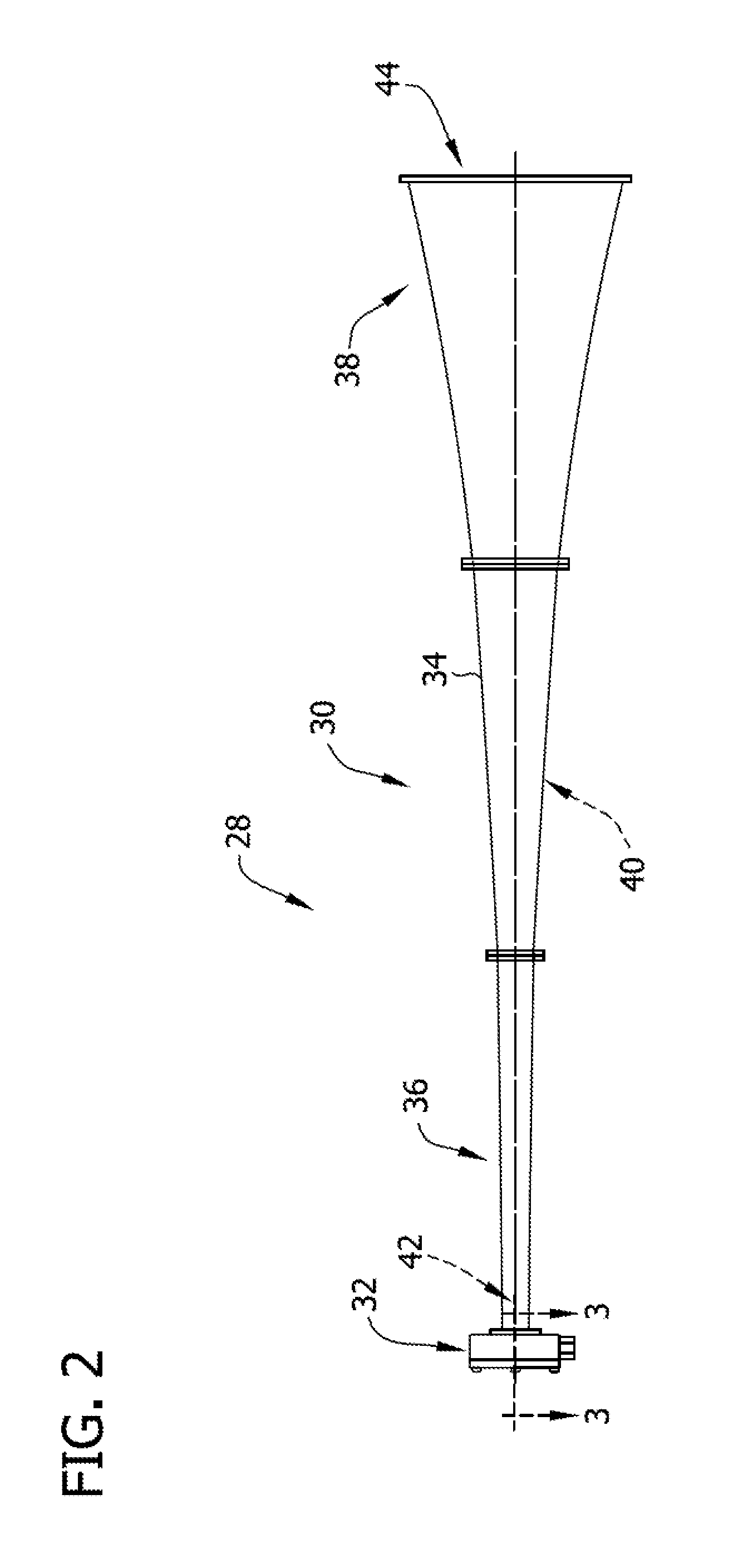
[0017]The exemplary methods and systems described herein overcome at least some disadvantages of known acoustic cleaning assemblies by providing a cleaning assembly that includes a sound generator that channels air from an inlet plenum to an outlet plenum across a diaphragm. Moreover, in the exemplary embodiment the diaphragm is positioned between the inlet and outlet plenums such that pressurized air is channeled across an outer surface of the diaphragm. In addition, a support assembly, positioned within the inlet plenum and / or the outlet plenum, and is coupled to the diaphragm to support the diaphragm within a cavity of the acoustic cleaning assembly.

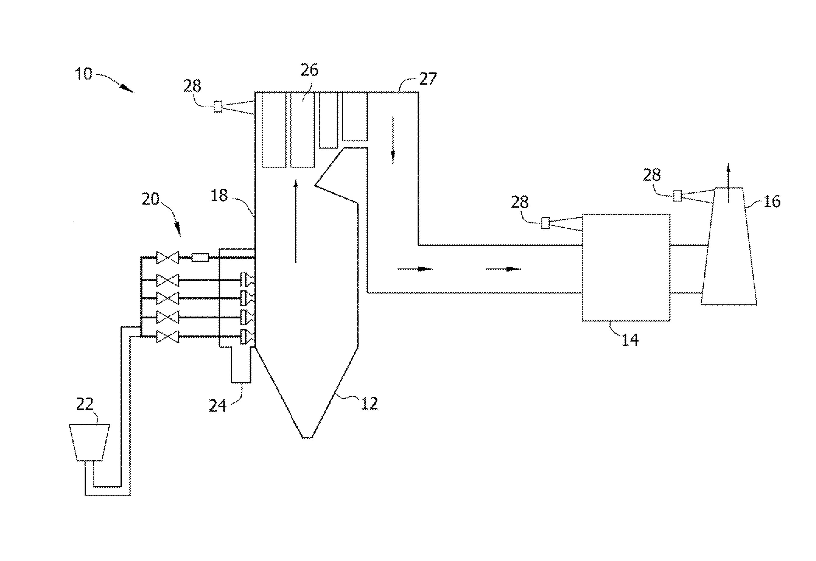
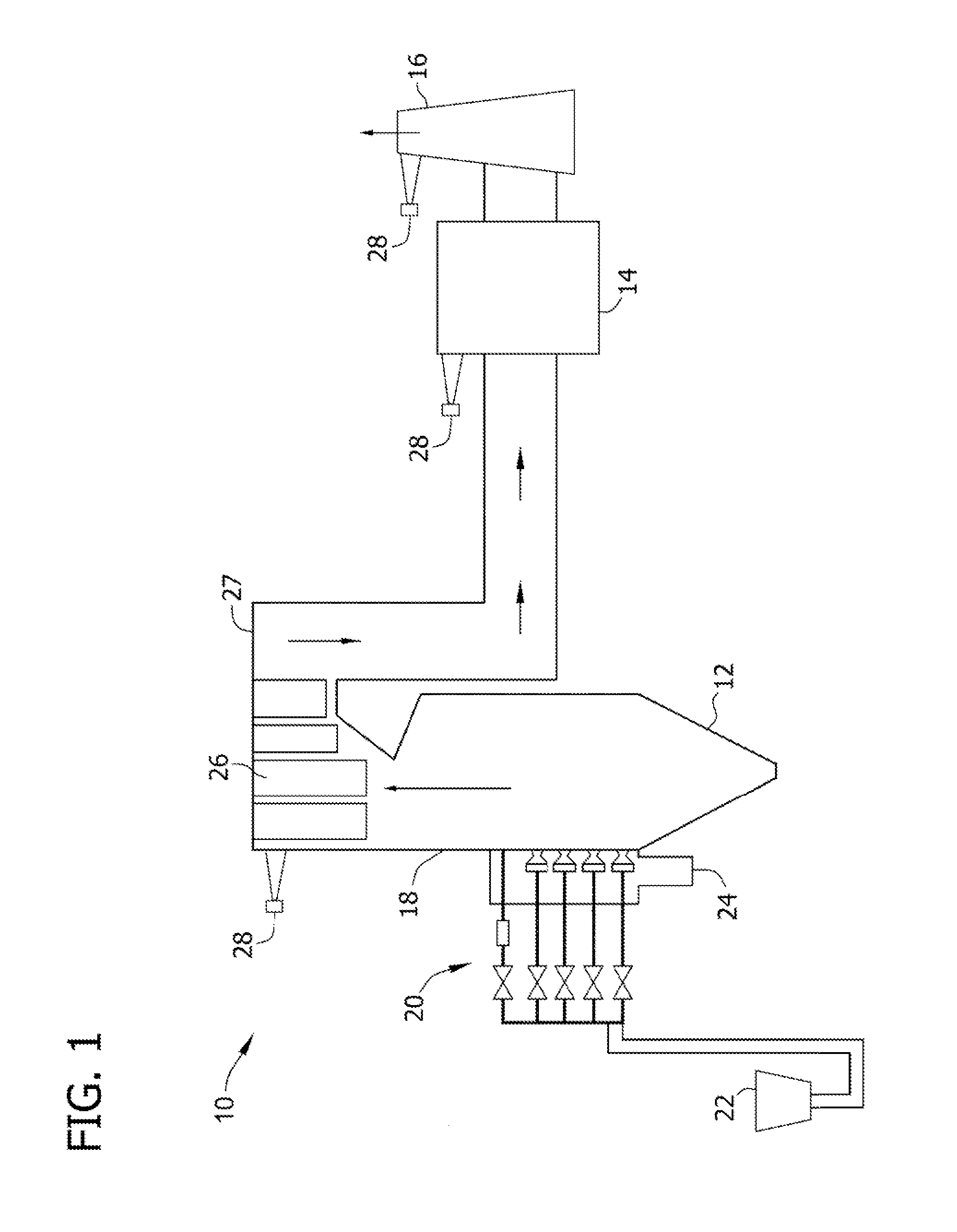
[0018]FIG. 1 is a schematic view of an exemplary power generation system 10 that generally includes a furnace 12, a particulate filter assembly 14, and an exhaust stack 16. Specifically, in the exemplary embodiment, furnace 12 includes a combustion assembly 18 that includes a burner assembly 20 that is configured to supply a predeterm...


PUM

PropertyMeasurementUnit
poweraaaaaaaaaa
pressureaaaaaaaaaa
impedanceaaaaaaaaaa

Abstract

An acoustic cleaning assembly that includes a horn assembly and a generator body that is coupled to the horn assembly. The generator body includes an inner surface that at least partially defines an outlet plenum, and an opening that extends in flow communication between the horn assembly and the outlet plenum. An end cap is coupled to the generator body and includes an inner surface that at least partially defines an inlet plenum. A diaphragm is coupled between the generator body and the end cap. The diaphragm channels air from the inlet plenum to the outlet plenum to facilitate generating sound waves within the outlet plenum.

Description

BACKGROUND OF THE INVENTION[0001]The subject matter described herein relates generally to turbine engines and, more particularly, to an acoustic cleaning assembly for use with power generation systems.[0002]At least some known power generation systems includes a furnace and / or boiler to generate steam that is used in a steam turbine generator. During a typical combustion process within a furnace or boiler, for example, a flow of combustion gases, or flue gases, is produced. Known combustion gases contain combustion products including, but not limited to, carbon, fly ash, carbon dioxide, carbon monoxide, water, hydrogen, nitrogen, sulfur, chlorine, arsenic, selenium, and / or mercury.[0003]At least some known power generation systems include a particulate collection device, such as a baghouse, for use in reducing an amount of combustion products within the flue gases. During operation, at least some known components of the power generation system, such as the baghouse, are subjected to...

Claims


Application Information

Patent Timeline
Patent Type & Authority Applications(United States)
IPC IPC(8): F01N3/021B23P11/00B08B3/12
CPCY10T29/49826G10K9/02F01D25/002
Inventor ZHANG, TIAN XUANCHAPIN, DAVID MICHAEL
Owner PARKER INTANGIBLES LLC
Why Eureka
Try Eureka