

Breathing Air Production and Distribution System
a technology of breathing air and distribution system, which is applied in the direction of respirators, lighting and heating apparatus, heating types, etc., can solve the problems of affecting the safety of people in and around the work environment, affecting the safety of workers, and requiring uncontaminated breathing air supply
- Summary
- Abstract
- Description
- Claims
- Application Information
AI Technical Summary
Benefits of technology
Problems solved by technology
Method used
Image

Examples
first embodiment
[0018]A. First Embodiment of Breathing Air Production and Filtration System
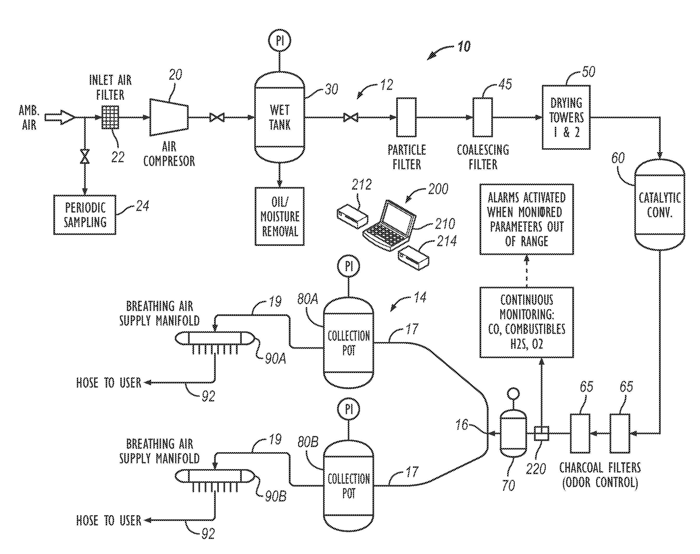
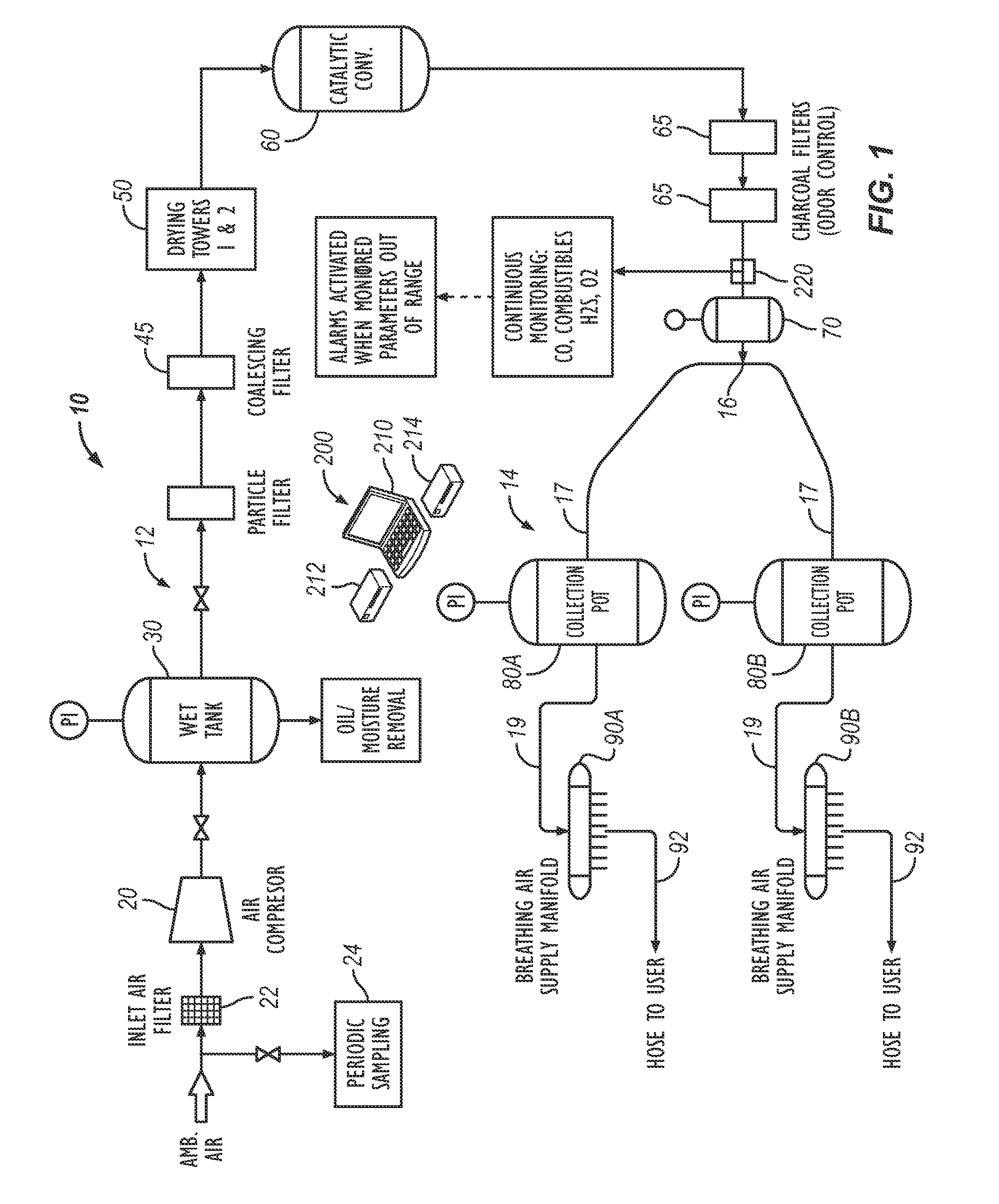
[0019]FIG. 1 illustrates a system 10 according to the present disclosure for producing filtered breathing air and delivering the breathing air to end users in a work environment. The system 10 has a generation assembly 12 that generates the breathing air from ambient air in a remote environment. To do this, the generation assembly 12 includes a compressor 20, a wet tank 30, a particle filter 40, a coalescing filter 45, drying towers 50, a catalytic converter 60, charcoal filters 65, and a dry tank 70. All of these components of the generation assembly 12 can be mounted on a skid or trailer, which can be positioned far from work areas.
[0020]A second part of the system 10 includes a distribution assembly 14 in communication with the generation assembly 12. The distribution assembly 14 receives the generated breathing air from the generation assembly 12 and delivers it to the end users located in work areas of a...
second embodiment
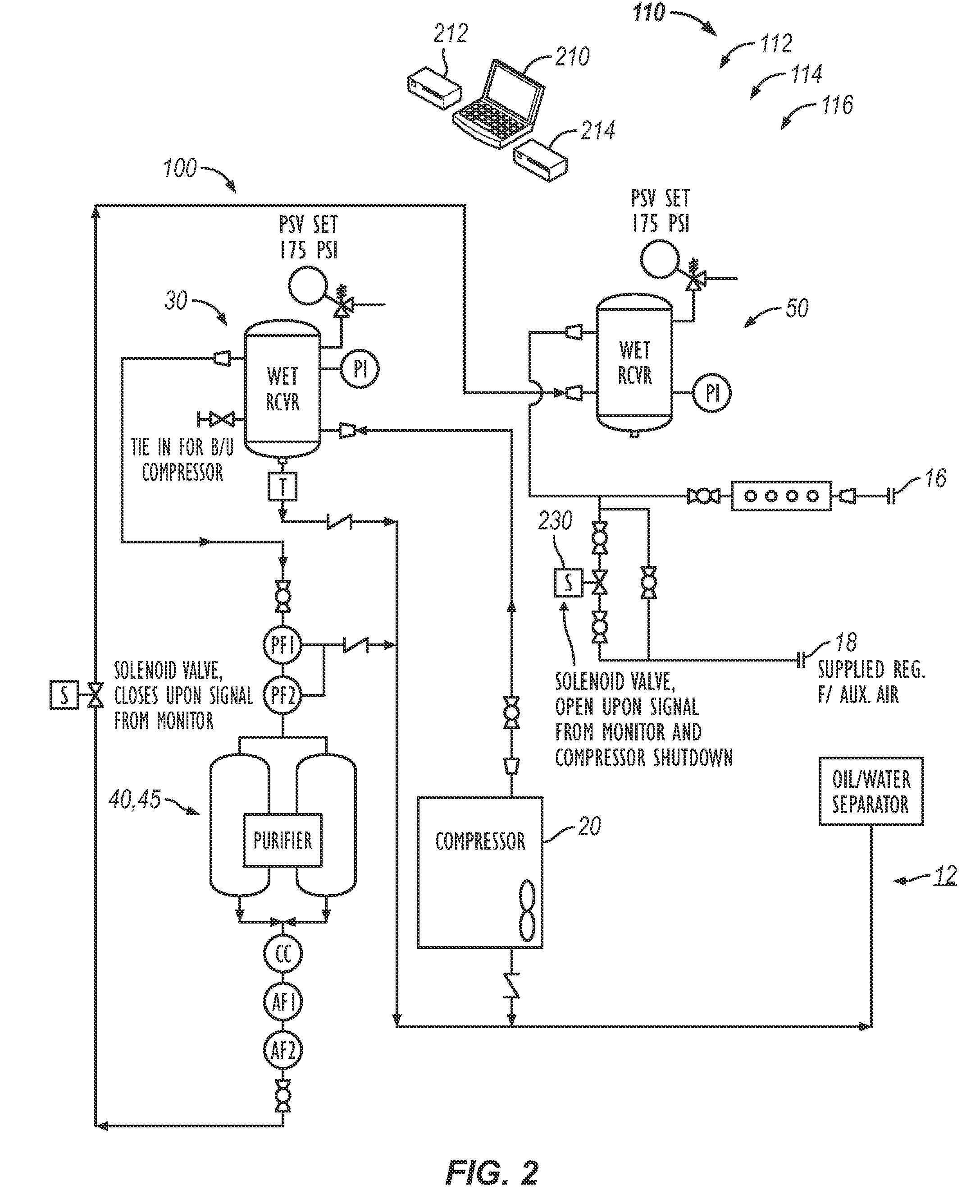
[0037]C. Second Embodiment of Breathing Air Production and Filtration System
[0038]FIGS. 4A-4C illustrate another arrangement of a breathing air production and filtration system 10 according to the present disclosure. As before, the system 10 has a breathing air generation assembly 12 (FIGS. 4A-4B) and a distribution assembly 14 (FIG. 4C). As noted before, the generation assembly 12 generates the breathing air and can be mounted on a skid or trailer. A discharge outlet 16 on the generation assembly 12 (FIG. 4B) can connect to a large hose 17 for communicating with the distribution assembly 14 (FIG. 4C). In general, this connection at the outlet 16 can be a 2-in. crow's foot connector.
[0039]As shown in FIGS. 4A-4B, the generation assembly 12 has a compressor 20, a wet tank 30, a particle filter 40, a coalescing filter 45, drying towers 50, a catalytic converter 60, charcoal filters 65, and a dry tank 70. A drying control 55 can be provided for the drying towers 50 to route generated b...
third embodiment
[0047]D. Third Embodiment of Breathing Air Production and Filtration System
[0048]FIGS. 5A-5C illustrate yet another arrangement of the disclosed system 10. This arrangement is similar to that described above in FIGS. 4A-4C. Here, the system 10 has two collection pots 80A-B as well as additional sensing features for the monitoring and control system 200. In particular, the alarm element transmitter 226 coupled to the flow controller 225 sends a wireless signal to the control unit 210 via a suitable wireless connection, although a wired connection could be used. The information communicated can be used by the control unit 210 for data logging and storage in the storage device 212. This can be beneficial in reviewing whether any events with contaminants occurred so issues with the system 10 can be resolved. The wireless signal can also be used by the control unit 210 to activate the automatic switch-over 230 to change to the reserve supply 400 and shut off the breathing air supplied by...
PUM
 Abstract
Description
Claims
Application Information