Method of manufacturing a component

a manufacturing method and component technology, applied in the direction of additive manufacturing processes, manufacturing tools, soldering devices, etc., can solve the problems of increasing set up time and long processing time, and achieve the effect of reducing optics set up time, reducing overall manufacturing processing time, and increasing deposition ra

Inactive Publication Date: 2012-10-25
ROLLS ROYCE PLC
View PDF50 Cites 60 Cited by
  • Summary
  • Abstract
  • Description
  • Claims
  • Application Information

AI Technical Summary

Benefits of technology

[0005]Hence a method of manufacture and apparatus which reduces optics setup time and reduces manufacturing time (i.e. material deposition time), is highly desirable.SUMMARY OF INVENTION
[0007]According to a first aspect of the present invention there is provided a method of manufacturing a component comprising the steps of directing a beam of energy to heat a working region of a substrate; adjusting the cross sectional shape of the beam to thereby generate a variety of predetermined cross sectional shapes of working region while the beam is being directed onto the substrate to thereby control the distribution of energy delivered to the substrate during the manufacturing process.
[0009]According to a second aspect of the present invention there is provided a method of manufacturing a component comprising the steps of directing a beam of energy to heat a working region of a substrate; adjusting the energy intensity profile of the energy beam during the manufacturing process to achieve a variety of predetermined energy distributions while the beam is being directed onto the substrate; to thereby control the distribution of energy delivered to the substrate during the manufacturing process.
[0012]Hence the cross sectional shape of the working region and the distribution of energy delivered to the working region can be varied throughout the manufacturing process, thereby reducing optics set up time and enabling increased deposition rates, thereby reducing the overall manufacturing processing time.

Problems solved by technology

This has the disadvantage that in a structure with a combination of large and fine detail, either the laser optics must be adjusted between completing the large detail and starting the fine detail, thereby increasing set up time between runs, or the configuration which enables fine detail is used for the large detail, which results in long processing times.

Method used


Image

  • Method of manufacturing a component
  • Method of manufacturing a component
  • Method of manufacturing a component

Examples


Embodiment Construction

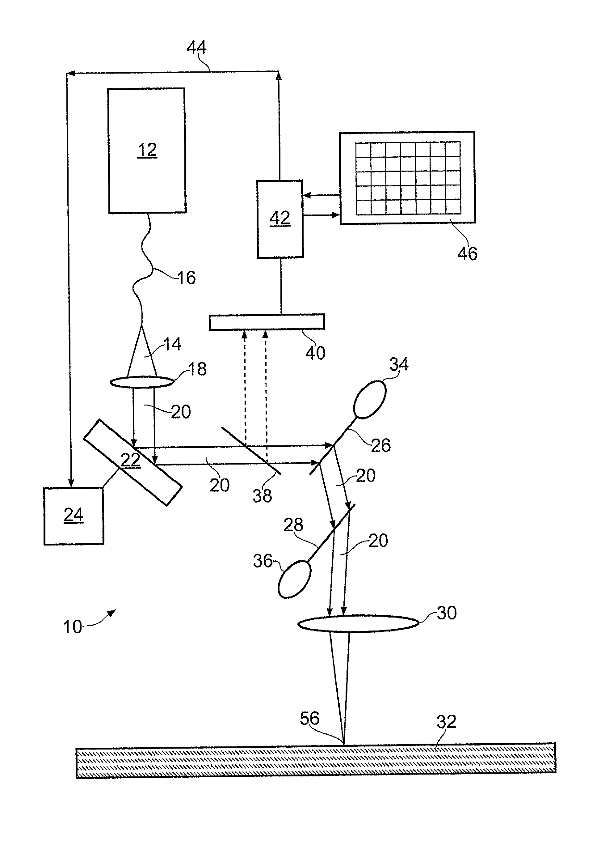
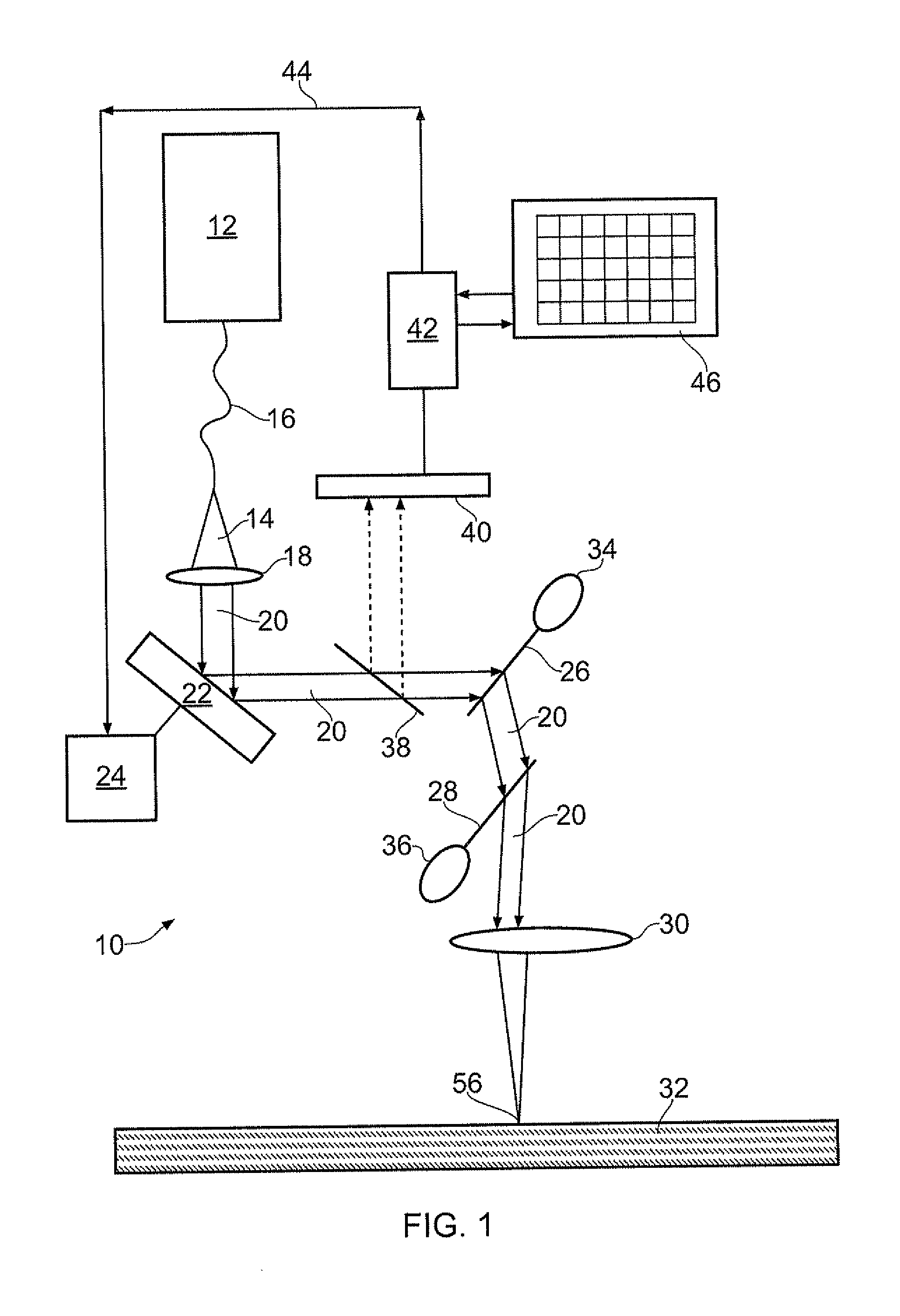
[0023]FIG. 1 shows a heating means 10, which comprises an energy beam source 12, in this case a laser 12, which delivers a beam of energy 14 via a fibre optic cable 16 to a collimating lens 18 to produce a beam of coherent energy 20. A deformable reflective means 22 for adjusting the cross sectional shape of the beam 20, for example a deformable mirror 22, is located in the path of the beam 20. The deformable reflective means 22 is also operable to adjust the energy intensity profile of the energy beam 20. The reflective profile of the deformable means 22 is controlled by an actuator 24. In the embodiment shown the deformable means 22 comprises a foil mirror which is actuated by a piezo-electrical control means 24. It may alternatively be hydraulically or pneumatically actuated. The deformable means 22 directs the energy towards an array of movable mirrors 26,28, which then directs the energy beam through a convergent lens 30 to focus the beam down to the correct size on the substra...


PUM

PropertyMeasurementUnit
distribution of energyaaaaaaaaaa
areaaaaaaaaaaa
energy intensityaaaaaaaaaa

Abstract

Apparatus for manufacturing a component and a method of manufacturing a component. The method comprises the steps of directing a beam of energy to heat a working region of a substrate and adjusting the cross sectional shape of the beam to thereby generate a variety of predetermined cross sectional shapes of working region while the beam is being directed onto the substrate. Thus the distribution of energy delivered to the substrate is controlled during the manufacturing process. The cross sectional shape and area of the beam is repeatedly monitored and compared to a library of predetermined cross sectional shape(s) and area(s).

Description

[0001]The present invention relates to a method of manufacturing a component.[0002]In particular it relates to manufacturing a component by directing a beam of energy from a heating means to heat a working region of a substrate.[0003]Manufacture of components by material deposition, for example by weld deposition or powder bed layer deposition, is known. In such processes a heating means (for example, a laser) is passed over a substrate, bringing a working region of the substrate to a molten state as it moves relative to the substrate. Powdered material is delivered to the molten region, brought to a molten state, and then cooled such that it solidifies and creates a solid structure along the direction of travel of the heating means.[0004]The shape of the working region is determined by the shape of the laser beam projected onto the substrate. The amount and distribution of heat delivered to the working region is determined by the energy intensity profile of the laser. The laser bea...

Claims


Application Information

Patent Timeline
Patent Type & Authority Applications(United States)
IPC IPC(8): B23K15/00
CPCB23K26/0643B23K35/0244B23K26/0732B23K26/0807B23K26/083B23K26/0869B23K26/1411B23K26/34B23K2201/18B23K2201/34B29C67/0066B29C67/0077B29C67/0085B23K26/3246B23K26/345B23K26/073B23K26/324B23K26/082B23K26/144B23K26/342B29C64/135B29C64/153B29C64/268B23K2101/18B23K2101/34B23K2103/30
Inventor CLARK, DANIELGRAFTON-REED, CLIVE
Owner ROLLS ROYCE PLC
Why Eureka
Try Eureka