Magnetic Resonance Signal Detection Using Remotely Positioned Receive Coils

a technology of magnetic resonance signal and receive coil, which is applied in the direction of using reradiation, geological measurements, sensors, etc., can solve the problems of large number of channels, insufficient quality of body coil, and inability to construct conventional cable traps in the cable, so as to reduce the signal-to-noise ratio, which is dependent on the amount of noise generated within the volume of the coil,

Active Publication Date: 2012-10-25
DEERFIELD IMAGING INC
View PDF3 Cites 34 Cited by
  • Summary
  • Abstract
  • Description
  • Claims
  • Application Information

AI Technical Summary

Benefits of technology

[0122]In such arrangements the cables are typically very long so that the absence of a cable at all is of increased advantage.
[0123]As the first co

Problems solved by technology

However in some cases the body coil does not provide an image of sufficient quality to meet the requirements and hence local coils must be used.
a) The number of channels is limited to the number of receivers in the system.
b) A large diameter cable bundle, such as an eighteen channel phased array coil which require 18 channel cables, containing 18 coaxial cables and at least 25 control wires, would be much too large to enable construction of the conventional cable trap in the cable.
c) It is difficult to build because the electrical components, such as the circuit board baluns and preamps, are complicated and time consuming to assemble by a skilled and experienced technician. These components require significant effort during design and construction to produce high quality images and to reduce the crosstalk between components.
d) The required mechanical components, such as the long cables,

Method used


Image

  • Magnetic Resonance Signal Detection Using Remotely Positioned Receive Coils
  • Magnetic Resonance Signal Detection Using Remotely Positioned Receive Coils
  • Magnetic Resonance Signal Detection Using Remotely Positioned Receive Coils

Examples


first embodiment

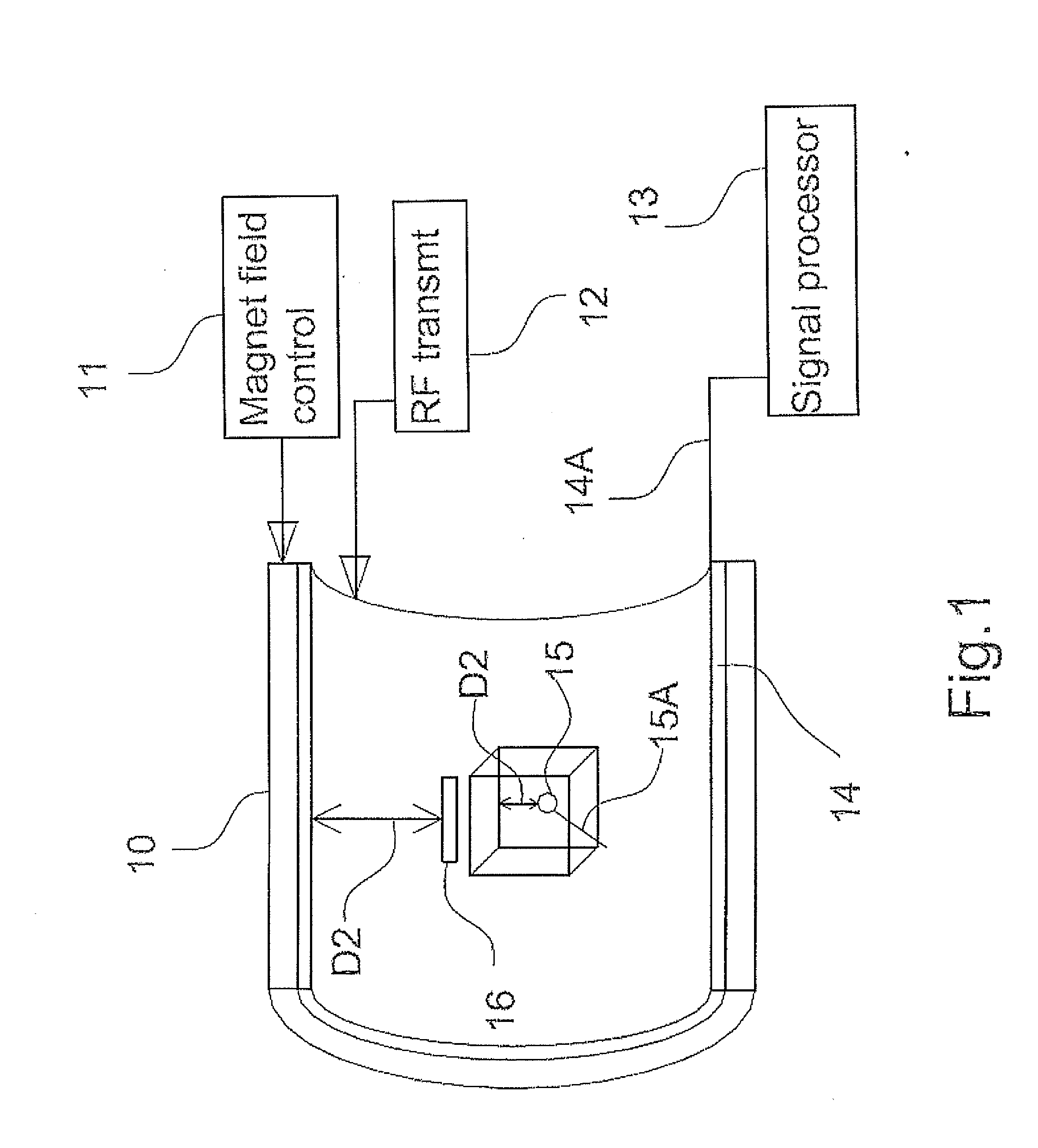
[0148]In the first embodiment shown in FIG. 1, the transmit coil is defined by the body coil 14. The receive coil arrangement comprises an innermost coil loop 15 located inside the body of the patient. This is inserted by a suitable support 15A which moves the coil 15 to the required location within the patient, for example within the heart or other organ to be imaged. The receive coil arrangement further comprises a first outer coil 16 located adjacent to the innermost coil 15 but outside the body. The coil 16 can be formed by a single loop but more preferably by a phased array of loops. The receive coil arrangement further comprises a second outer coil defined by the body coil 14 surrounding the coil 16. In other arrangements a separate coil can be used for the second outer coil. In any case, the second outer coil has a signal communication cable 14A connected to the signal processing system 13 for transferring the MR signal therein to the signal processing system.

[0149]In FIG. 4,...

second embodiment

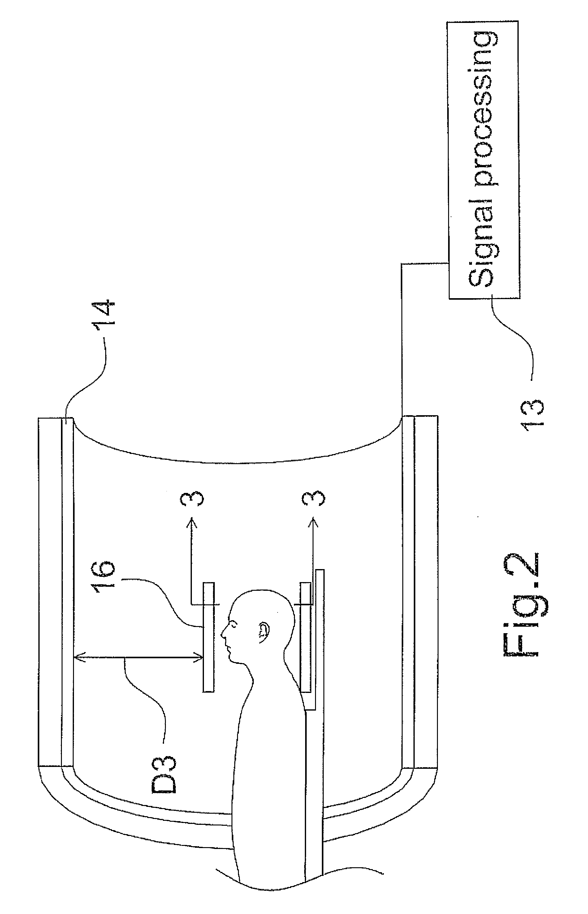
[0158]In the second embodiment shown in FIG. 2, there are only two coils defined by the body coil 14 and the coil 16. Thus the signal is obtained primarily by the coil 16 and is transferred inductively to the coil 14 for cable transmission to the signal processing system 13.

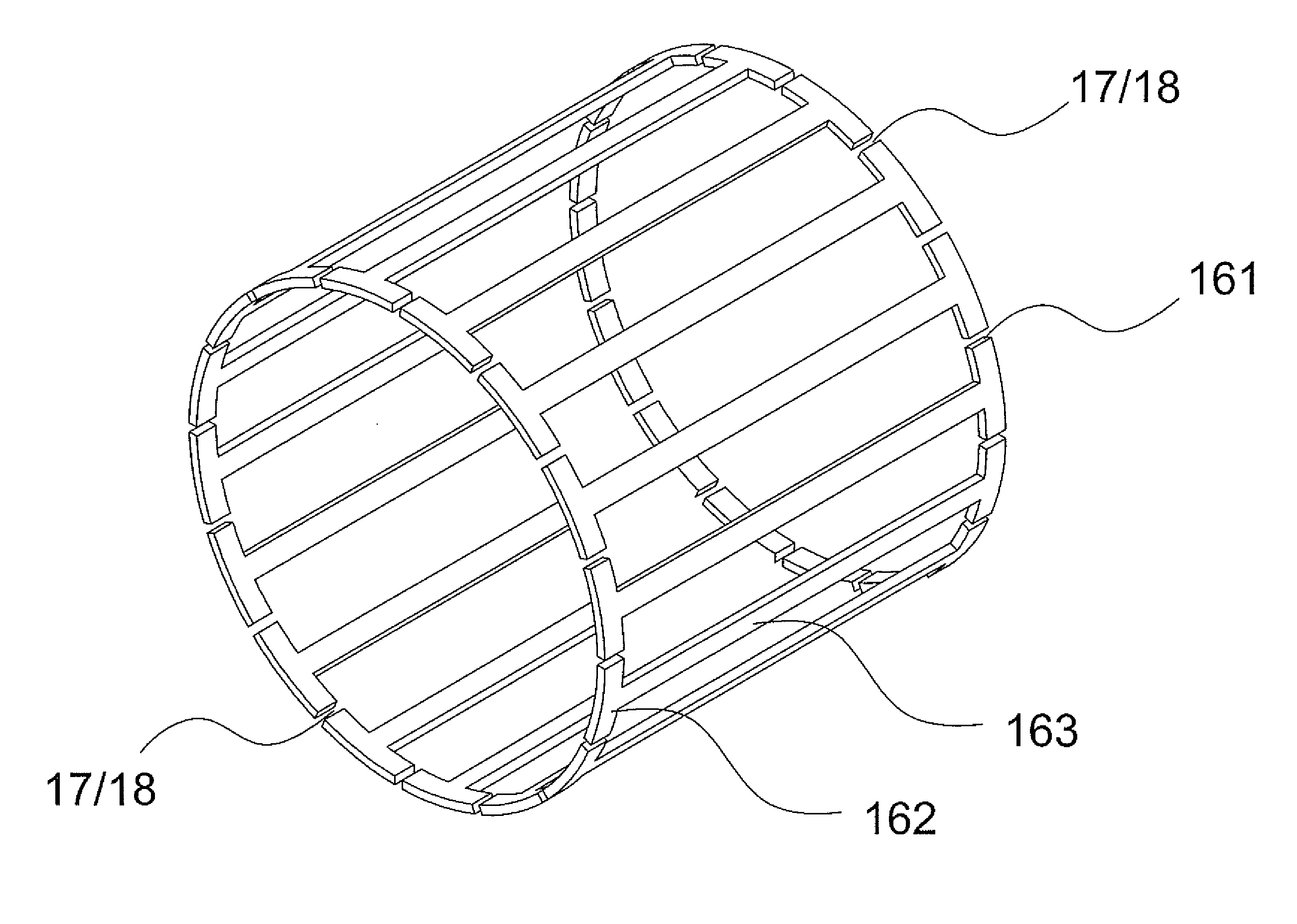
[0159]In this embodiment, the coil 16 is a head coil including a bottom section 16X underneath the head and a top section 16Y on top of the head. One or both sections can be flexible since each is formed simply by a carrier substrate 16Z and the conductive loops. In this embodiment 6 loops 16A to 16F are shown but different numbers can be used. Each loop includes circuit elements defining the tuning component 17 and the switch 18.

[0160]In FIG. 5 is shown a further embodiment wherein the body coil is absent or is not used where there is a separate transmit coil 20 and the coil 23 is connected to the signal processing system by a cable 13A.

[0161]Turning now to the embodiment shown in FIG. 6 there is shown an arrang...


PUM


Abstract

The receive coil arrangement includes an inner local volume coil adjacent the part to be imaged so as to maximize the received MR signal and an outer coil, which may be the built in body coil of the magnet, connected by cable to the signal processing system. Both the coils are individually tuned to the common resonant frequency and the local volume coil include an arrangement to halt current flow therein during the transmit stage. The local volume coil has no cable and is arranged to communicate the MR signal therein to the signal processing system through the outer coil by inductive coupling to the outer coil. Despite inherent losses by interfering with the tuning of the loops and in the inductive coupling this magnifies the MR signal and makes the local volume coil wireless.

Description

[0001]This application is a continuation in part application of application Ser. No. 13 / 090816 filed Apr. 20, 2011.[0002]This invention relates to an RF receive coil assembly for MR imaging.BACKGROUND OF THE INVENTION[0003]As is well known, MR imaging uses an RF receive coil to receive the signals emitted by the subject under test in response to excitation of a selected volume of the subject which is generated by a RF transmit coil, such as the built in body coil. Thus the Gradient coils generate controlled variations in the main magnetic field (B0) magnetic field to produce selected spatial excitation volume and the signal emitted by that selected volume is picked up by the receive coil arrangement and transmitted to a signal processing system.[0004]The receive coil arrangement can comprises a single coil loop or element or it can include a series of loops arranged in a pattern around the part of the subject to be imaged.[0005]MR systems provide a built in body coil in the magnet c...

Claims


Application Information

Patent Timeline
IPC IPC(8): G01R33/44
CPCG01R33/34007G01R33/34076G01R33/34084G01R33/3415G01R33/34G01R33/3642G01R33/3657G01R33/3664G01R33/3692G01R33/3635
Inventor ZHU, HAOQINPETROPOULOS, LABROSSCHELLEKENS, WAYNESAUNDERS, JOHNLANG, MICHAELFALLAH-RAD, MEHRAN
Owner DEERFIELD IMAGING INC
Why Eureka
Try Eureka