Driving circuit for vibration apparatus

a technology of driving circuit and vibration apparatus, which is applied in the direction of piezoelectric/electrostrictive device details, instruments, television systems, etc., can solve the problems of degradation of foreign particle removal performance, and achieve the effects of reducing voltage amplitude fluctuations, low boost ratio, and increasing harmonic signals

Inactive Publication Date: 2012-11-01
CANON KK
View PDF19 Cites 16 Cited by
  • Summary
  • Abstract
  • Description
  • Claims
  • Application Information

AI Technical Summary

Benefits of technology

[0039]Therefore, conventionally the fluctuations of the voltage amplitude are designed to be reduced by reducing the inductance value.
[0040]However, this provides a low boost ratio for the alternating voltage and increases the harmonic signals.

Problems solved by technology

These harmonic signals affect vibrations excited on the vibration member 501, resulting in degradation of foreign particle removal performance due to traveling wave disturbances and damage to the optical member 502 due to increases in vibration amplitude.

Method used


Image

  • Driving circuit for vibration apparatus
  • Driving circuit for vibration apparatus
  • Driving circuit for vibration apparatus

Examples


first embodiment

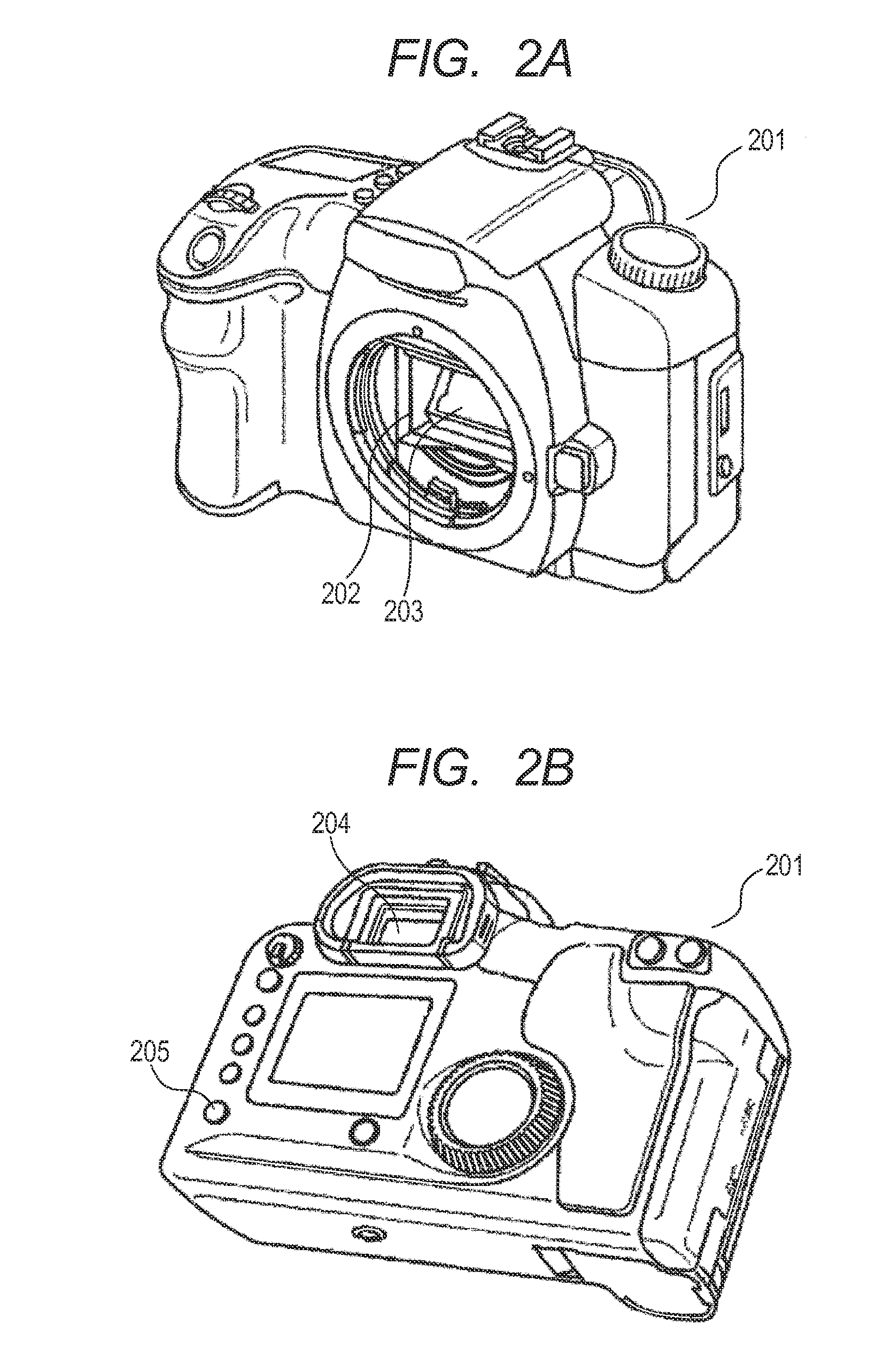
[0076]In a first embodiment, description will be given of a configuration example in which a driving circuit for a vibration apparatus according to the present invention is mounted as a foreign particle removal apparatus in a camera which is an optical instrument (i.e., in this example, the vibration apparatus is used as a foreign particle removal apparatus).

[0077]Incidentally, although a configuration example in which a vibration apparatus is mounted in a camera is described in the present embodiment, this is not restrictive.

[0078]Moreover, the present invention is applicable to a driving circuit of a foreign particle removal apparatus provided in another optical instrument such as a facsimile machine, a scanner, a projector, a copier, a laser beam printer, an inkjet printer, a lens, binoculars or an image display apparatus.

[0079]A driving circuit for a vibration apparatus according to the present embodiment is configured to apply alternating voltages to piezoelectric elements whic...

second embodiment

[0187]As a second embodiment, a configuration example of a driving circuit for a vibration apparatus of a different form from the first embodiment will be described.

[0188]The present embodiment differs in configuration from the first embodiment in that two vibration modes are excited alternately on the vibration member 501.

[0189]Incidentally, the driving circuit of the foreign particle removal apparatus is the same as the first embodiment and the present embodiment is distinguished for a method for setting frequency information and phase information on the controller of the control apparatus.

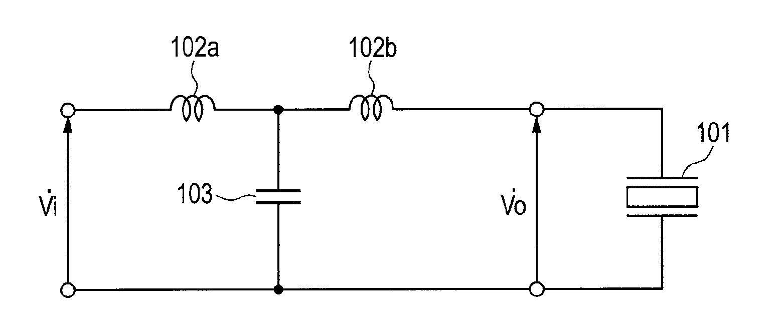
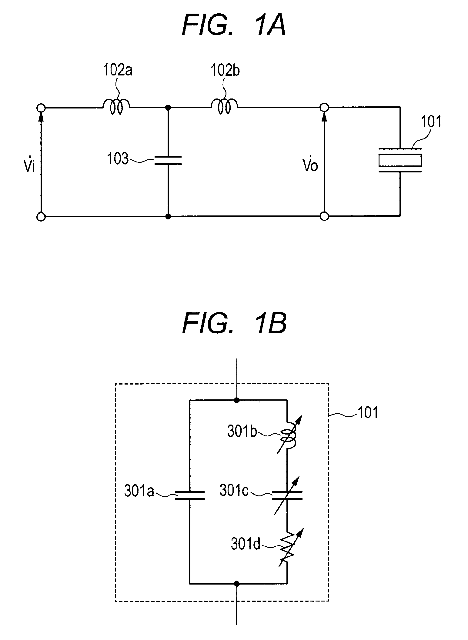
[0190]The driving circuit according to the present embodiment will be described below with reference to FIGS. 1A and 1B.

[0191]FIG. 1A is a diagram illustrating the driving circuit of the foreign particle removal apparatus according to the second embodiment. In the configuration of the driving circuit, two inductors 102a and 102b are connected in series with the piezoelectric element 101 (i.e., i...

third embodiment

[0220]In a third embodiment, description will be given of a configuration example in which a driving circuit for the vibration apparatus according to the present invention is applied to a vibration type actuator (i.e., an example in which the vibration apparatus is configured to be a vibration type actuator).

[0221]The driving circuit according to the present invention is widely applicable in addition to the foreign particle removal apparatus show in the first embodiment and second embodiment. For example, the driving circuit is applicable as a driving circuit of a vibration type actuator.

[0222]FIG. 11 shows a control apparatus in the case where a vibration type actuator is used as a vibration apparatus. As in the case of the first and second embodiments, control apparatus is equipped with at least a driving circuit.

[0223]A velocity deviation detector 401 accepts as inputs a velocity signal obtained by a velocity detector 407 such as an encoder and a target velocity from a controller...


PUM


Abstract

The present invention provides a driving circuit for a vibration apparatus which drives an object using a vibration wave generated by an electro-mechanical energy conversion element is equipped with an electrical resonance circuit, and which is capable of reducing harmonic components of an alternating voltage applied to an electro-mechanical energy conversion element. The electrical resonance circuit includes an electrostatic capacity of the conversion element, plural inductors connected in series with the conversion element, and a capacitor connected at one end between the plural inductors and connected in parallel with the conversion element. The electrical resonance circuit has at least two resonance frequencies including a first frequency and a second frequency and satisfies the relation:
f1<fd<f2
where f1 is the first frequency, f2 is the second frequency, and fd is a frequency of an alternating voltage.

Description

BACKGROUND OF THE INVENTION[0001]1. Field of the Invention[0002]The present invention relates to a driving circuit for a vibration apparatus.[0003]2. Description of the Related Art[0004]Recently, in imaging apparatus which are optical instruments, with improvement in the resolution of optical sensors, dirt and other foreign particles attaching to an optical system during use have come to affect photographic images.[0005]In particular, the resolution of imaging devices used for video cameras and still cameras have been improving remarkably.[0006]Consequently, if outside dust or inside wear debris produced on a mechanical sliding surface attaches to an optical part such as an infrared cut filter or optical low pass filter placed near the imaging device, since images do not blur much on a surface of the imaging device, the dust might appear in photographic images. Also, an imaging portion of copiers, facsimile machines and other similar optical instruments reads (scans) a flat document...

Claims


Application Information

Patent Timeline
Patent Type & Authority Applications(United States)
IPC IPC(8): H02N2/06G03B17/02
CPCH04N5/2171G03B17/14H04N23/811
Inventor SUMIOKA, JUN
Owner CANON KK
Why Eureka
Try Eureka