Motor control unit and vehicle steering system

Active Publication Date: 2012-11-01
JTEKT CORP
View PDF8 Cites 19 Cited by
  • Summary
  • Abstract
  • Description
  • Claims
  • Application Information

AI Technical Summary

Benefits of technology

[0011]The value (sign) of the voltage (voltage parameter) that is applied to the motor changes in accordance with the motor rotation angle. Therefore, the duration (first or second duration) of the state where the first or second determination condition is satisfied due to the influence of inductive voltage is determined based on a rotation period of the motor during high-speed rotation. Therefore, when the first or second duration exceeds the reference period that is set based on the rotati

Problems solved by technology

However, even when no current-carrying failure has occurred, if the motor is rotating at a high speed, a high inductive voltage is generated, which may prevent application of electric current to the motor.
However, in a state where a current-carrying failure has occurred in an electric power supply path, the resistance value of the electric power supply path is infinite in theory.
Therefore, it is not possible to calculate an appropriate inductive voltage valu

Method used


Image

  • Motor control unit and vehicle steering system
  • Motor control unit and vehicle steering system
  • Motor control unit and vehicle steering system

Examples


first embodiment

[0025]Hereafter, a first embodiment in which the invention is applied to a vehicle steering system including a steering force assisting device will be described with reference to the accompanying drawings.

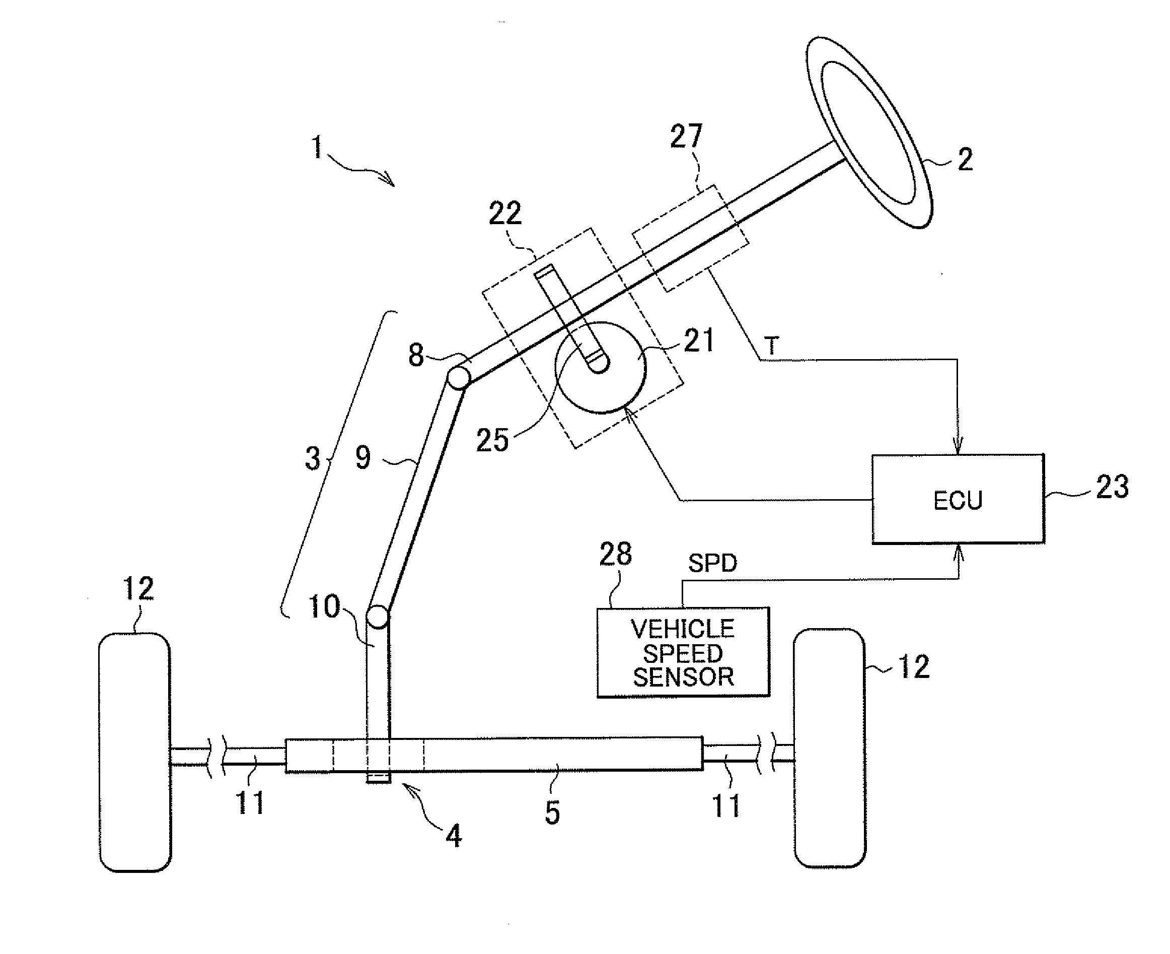
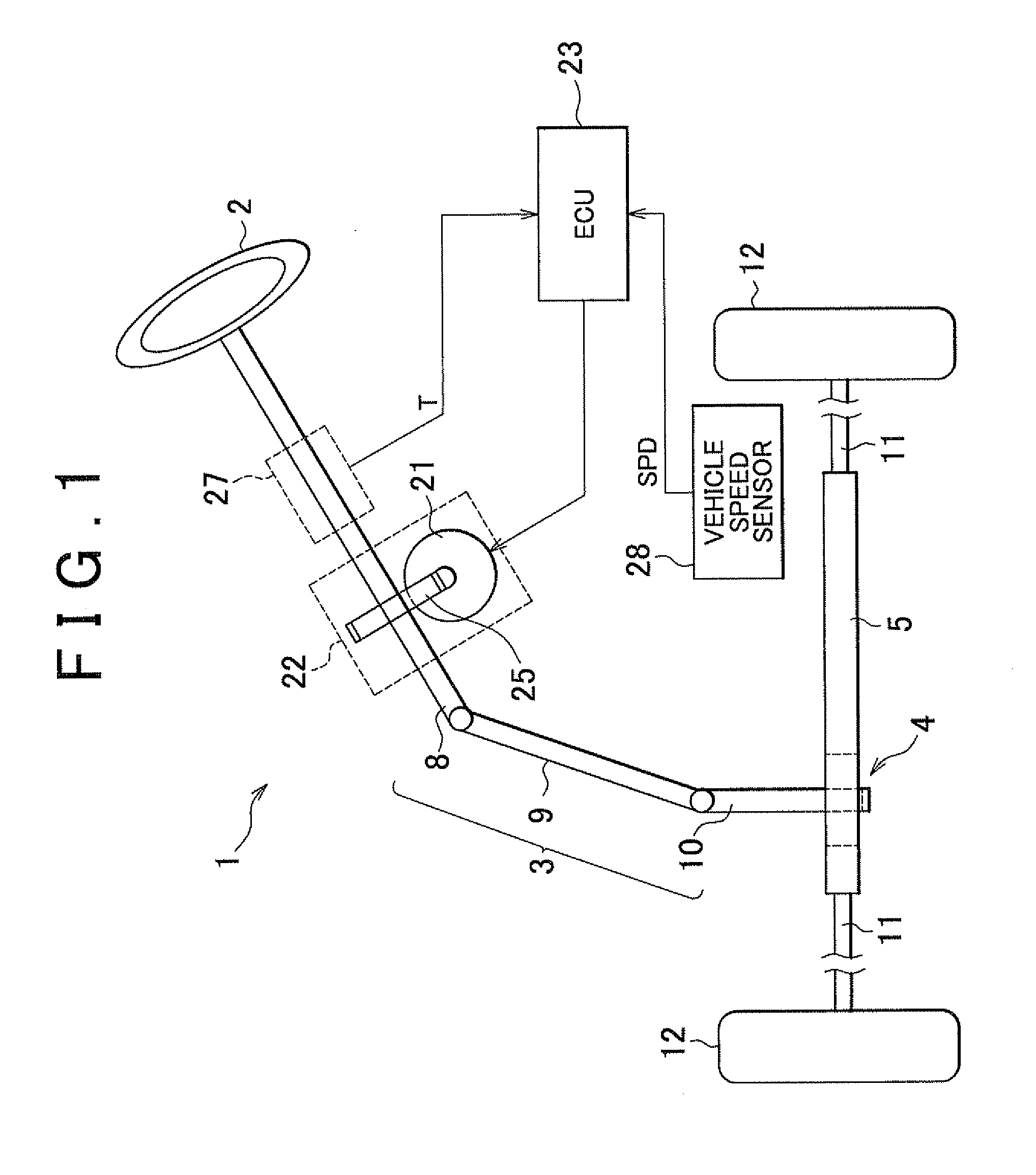
[0026]In a vehicle steering system (EPS) 1 shown in FIG. 1, a steering shaft 3 to which a steering wheel 2 is fixed is coupled to a rack shaft 5 via a rack and pinion mechanism 4. The rotation of the steering shaft 3 resulting from a steering operation is converted to a reciprocal linear motion of the rack shaft 5 by the rack and pinion mechanism 4. The steering shaft 3 is formed by coupling a column shaft 8, an intermediate shaft 9, and a pinion shaft 10 to each other. The reciprocal linear motion of the rack shaft 5 resulting from the rotation of the steering shaft 3 is transmitted to knuckles (not shown) via tie rods 11 coupled to respective ends of the rack shaft 5. Thus, the steered angle of steered wheels 7 is changed, that is, the traveling direction of a vehicle is changed....

second embodiment

[0075]Next, the procedure of current-carrying failure detection executed by the current-carrying failure detection unit 71 will be described with reference to the flowchart shown in FIG. 8. The current-carrying failure detection unit 71 acquires the power supply voltage Vps, the phase current value Ix of the determination target phase and the duty command value αx of the determination target phase (step 301). When the power supply voltage Vps is higher than or equal to the predetermined power supply voltage value Vth (YES in step 302) and the phase current value Ix is smaller than or equal to the predetermined current value Ith (YES in step 303), the current-carrying failure detection unit 71 determines whether the timer value t of the timer is smaller than or equal to a predetermined timer value tth that indicates the measuring period (step 304). At the time of turning on the ignition, the timer value t is set at zero. Subsequently, when the timer value t is smaller than or equal ...


PUM


Abstract

In a motor control unit, a current-carrying failure detection unit determines a first determination condition and a second determination condition. The current-carrying failure detection unit measures a duration of a state where the first determination condition is satisfied, and a duration of a state where the second determination condition is satisfied. When the first or second duration exceeds a predetermined reference period, the current-carrying failure detection unit determines that a current-carrying failure has occurred.

Description

INCORPORATION BY REFERENCE[0001]The disclosure of Japanese Patent Application No. 2011-100897 filed on Apr. 28, 2011 including the specification, drawings and abstract, is incorporated herein by reference in its entirety.BACKGROUND OF THE INVENTION[0002]1. Field of the Invention[0003]The invention relates to a motor control unit and a vehicle steering system.[0004]2. Description of Related Art[0005]A motor control unit that controls a brushless motor used in, for example, a vehicle steering system has the function of detecting a current-carrying failure, such as a wire disconnection, in an electric power supply path to the motor. Generally, such a current-carrying failure is detected in the following manner. First, an attempt to apply electric current to the motor is made. Then, if a detected actual current value indicates a non-current carrying state despite the attempt to apply electric current to the motor, it is determined that a current-carrying failure has occurred. Whether an...

Claims


Application Information

Patent Timeline
IPC IPC(8): H02P7/00B62D5/04B62D6/00B62D119/00H02P6/06H02P6/08H02P6/12H02P6/18H02P6/182H02P6/28H02P21/00H02P21/18H02P21/22H02P21/24H02P27/06H02P27/08
CPCH02P29/023B62D5/0487H02P29/0243B62D5/0481G01R31/343H02P6/12H02P29/032H02P29/0241
Inventor TAKAHASHI, TOSHIHIROMIKAMO, SATORUKAWAMURA, HIROSHIHASEGAWA, JUNTOMITA, AKIHIRONAMBU, AKIRA
Owner JTEKT CORP
Why Eureka
Try Eureka