Method and laser device for generating pulsed high power laser light

a laser light and laser light technology, applied in laser optical devices, laser details, electrical apparatus, etc., can solve the problems of optical non-linearity, limited circulating power, and limitation of circulating power, so as to reduce the reflectivity loss in the enhancement cavity, increase the average circulating power, and enhance the effect of the enhancement cavity

Inactive Publication Date: 2012-11-01
MAX PLANCK GESELLSCHAFT ZUR FOERDERUNG DER WISSENSCHAFTEN EV
View PDF3 Cites 5 Cited by
  • Summary
  • Abstract
  • Description
  • Claims
  • Application Information

AI Technical Summary

Benefits of technology

[0013]According to a further advantage of the invention, the number of cavity mirrors can be freely selected in dependency on practical application conditions. Preferably, the enhancement cavity comprises at least five cavity mirrors being arranged as a non-crossed ring resonator. Typically, the cavity mirrors comprise plane mirrors.
[0014]If a focal point is to be created along the light path in the enhancement cavity, e.g. for an interaction of the cavity pulse(s) with an optically non-linear medium or electrons, two neighbouring mirrors of the cavity mirrors comprise curved focusing mirrors being configured for focusing the cavity pulses there between. Preferably, the curved focusing mirrors comprise off-axis parabolas. The remaining cavity mirrors comprise plane mirrors.
[0015]As a preferred example, the enhancement cavity comprises eight cavity mirrors including two curved focusing mirrors. The inventors have found that with eight cavity mirrors various design options are available, e.g. with 60° or 70° oblique incidence, while reflectivity loss in the enhancement cavity can minimized.
[0016]The invention has a further essential advantage in terms of increasing the average circulating power in the enhancement cavity. According to a particularly preferred embodiment of the invention, the laser light pulses can be coherently added to a plurality of N cavity pulses (N≧2) circulating in the enhancement cavity. To this end, at least one of the pulse repetition rate (frep) of the laser source device and the cavity length (L) of the enhancement cavity are adjusted such that L=N*(c / frep), c being the speed of light in the enhancement cavity. The N cavity pulses provide the pulsed laser light to be generated, e.g. for X-ray generation. Preferably, the laser light pulses are coherently added to at least eight cavity pulses circulating in the enhancement cavity.
[0017]While loading of the enhancement cavity with 2 or more cavity pulses is known as such from U.S. Pat. No. 6,038,055, the inventive combination with irradiating the cavity mirrors under the oblique incidence yields an essential advantage in terms of the repetition rate of the cavity pulses. Due to the reduced risk of overheating the cavity mirrors, the repetition rate of the cavity pulses can be at least 100 MHz, preferably at least 325 MHz, in particular at least 500 MHz, or even 1 GHz or more, resulting in an increased average power circulating in the enhancement cavity.
[0018]Advantageously, an average power of the pulsed laser light created by the inventive coherent pulse addition can be adjusted by controlling the number N of cavity pulses circulating in the enhancement cavity. Accordingly, the average power can be selected in dependency on requirements of the particular application, e.g. for generating soft or hard X-rays, or for laser spectroscopy (pump-probe-experiments). To this end, a power control device can be provided being arranged for controlling the number N of cavity pulses circulating in the enhancement cavity.

Problems solved by technology

The conventional generation of pulsed laser light using a passive enhancement cavity has limitations in terms of circulating power and photon flow density.
However, there is still a limitation as to the circulating power.
Optical non-linearity in a mirror coating or impurities on a mirror surface may yield an increased temperature or destructions on the mirror surface due to microscopic burning spots.
Therefore, the conventional pulsed laser light generation is limited to an average power below 5 kW.

Method used


Image

  • Method and laser device for generating pulsed high power laser light
  • Method and laser device for generating pulsed high power laser light
  • Method and laser device for generating pulsed high power laser light

Examples


Embodiment Construction

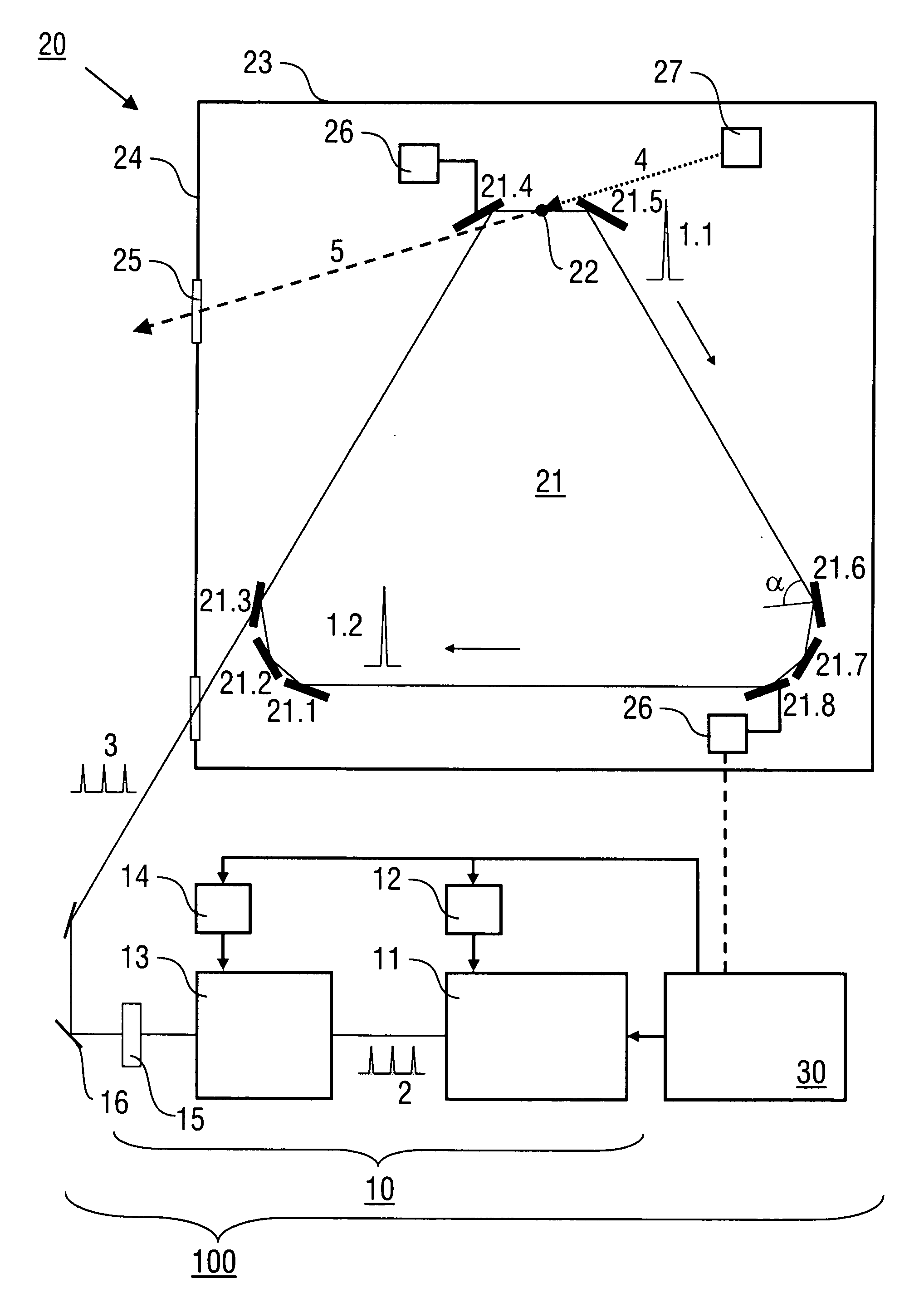
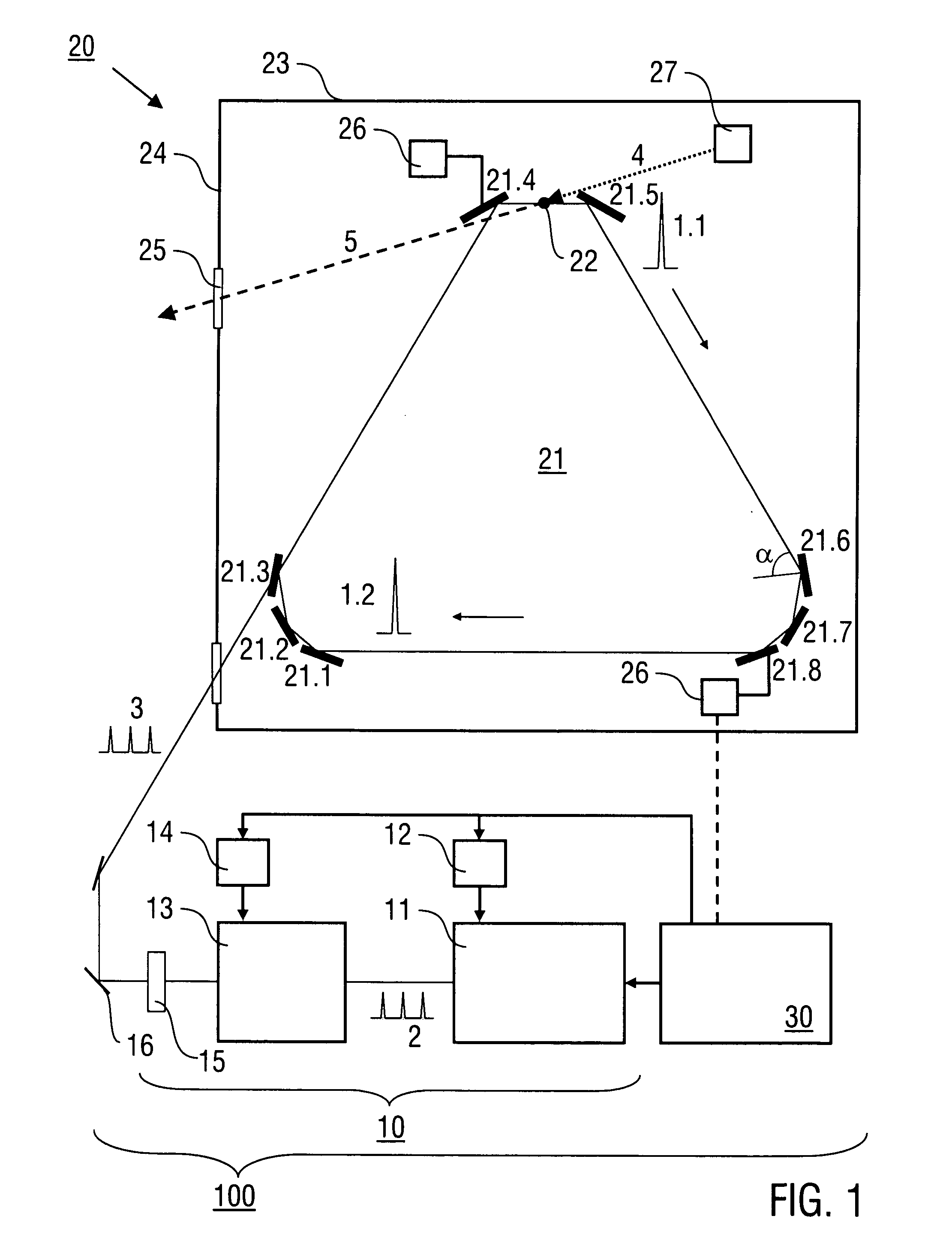
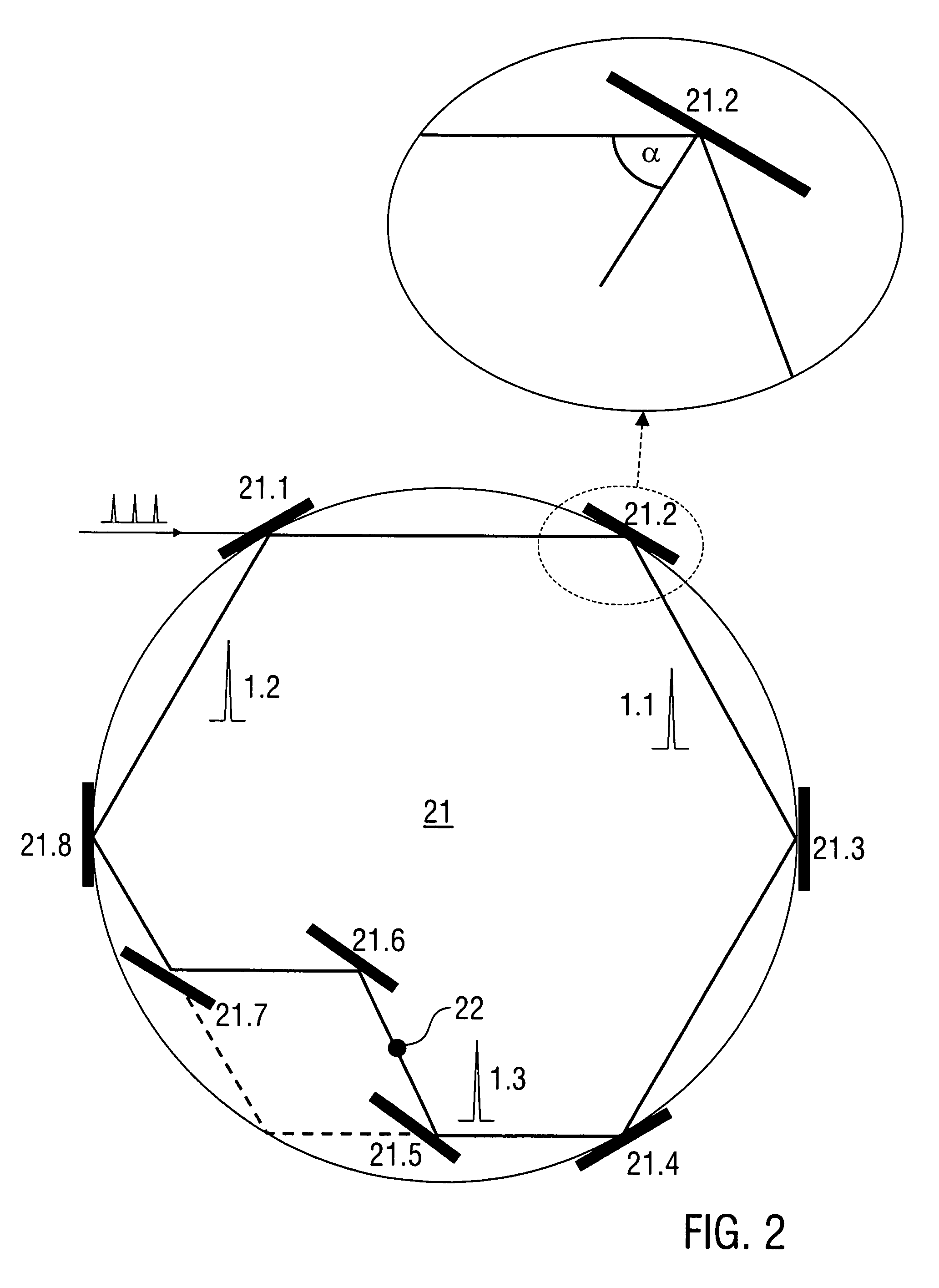
[0025]Embodiments of the invention are described in the following with exemplary reference to enhancement cavities having eight cavity mirrors. It is emphasized that the invention can be implemented in an analogue manner with a lower number, e.g. five to seven, or a larger number of cavity mirrors, e.g. nine or ten or even more. The cavity geometry and the angle of incidence at the cavity mirrors can be selected by experiment or by numerical design of the optical set-up based on available software solutions.

[0026]Preferred features of the invention are described for illustrating in particular the concepts of oblique incidence, irradiation with s-polarization, loading the enhancement cavity with at least two cavity pulses and passive repetition rate multiplication. Further features of the method of generating pulsed laser light and of the laser device, in particular with regard to the design and adjustment of an input coupling mirror, the synchronisation of the laser source device an...


PUM


Abstract

A method of generating pulsed laser light (1) comprises the steps of providing laser light pulses (2, 3) having a predetermined pulse repetition rate (frep) with a laser source device (10), coupling the laser light pulses into an enhancement cavity (21) with a plurality of cavity mirrors (21.1, 21.2, . . . ) and a predetermined cavity length (L), and coherent addition of the laser light pulses (2) in the enhancement cavity so that at least one cavity pulse (1.1, 1.2, . . . ) is formed, wherein the at least one cavity pulse (1.1, 1.2, . . . ) circulating in the enhancement cavity (21) irradiates all of the cavity mirrors (21.1, 21.2, . . . ) with an angle (α) of incidence of more than 45°. Furthermore, a laser device (100) being configured for conducting the method is described.

Description

SUBJECT OF THE INVENTION[0001]The invention relates to a method of generating pulsed laser light by coherent addition of laser light pulses in an enhancement cavity. Furthermore, the invention relates to a laser device comprising a laser source device and an enhancement cavity. Applications of the invention are available in the technical fields of generating high harmonic pulses of soft X-rays, generating hard X-rays by an interaction of laser pulses with relativistic electrons, generating of THz-radiation and laser spectroscopy (pump-probe-experiments).TECHNICAL BACKGROUND[0002]Generating X-rays on the basis of an interaction of laser light with a target material or electrons requires extremely high photon flow densities as the efficiency of the X-ray generating process is low (about 10−6). High photon flow densities can be provided with laser pulses generated by active amplification or by coherent addition in a passive resonator (see e.g. C. E. Clayton et al. in “Nuclear Instrumen...

Claims


Application Information

Patent Timeline
Patent Type & Authority Applications(United States)
IPC IPC(8): H01S3/10
CPCH01S3/005H01S3/0057H01S4/00H01S3/1392H01S3/0959
Inventor KRAUSZ, FERENCFILL, ERNSTRAUSCHENBERGER, JENSPUPEZA, IOACHIM
Owner MAX PLANCK GESELLSCHAFT ZUR FOERDERUNG DER WISSENSCHAFTEN EV
Why Eureka
Try Eureka