Optical element for reflection of UV radiation, method for manufacturing the same and projection exposure apparatus comprising the same

a technology of optical elements and radiation, applied in the field of optical elements, can solve the problems of limited coating parameters, inability to produce aluminum layers, and inability to form aluminum layers by sputtering, and achieve the effects of increasing the overall reflectance of the optical element, low surface roughness, and cost-effectiveness

Active Publication Date: 2010-11-18
CARL ZEISS SMT GMBH
View PDF11 Cites 15 Cited by
  • Summary
  • Abstract
  • Description
  • Claims
  • Application Information

AI Technical Summary

Benefits of technology

[0016]The inventors have found that it is possible to form a reflective aluminum layer with a (111)-plane orientation using a production process, in particular heteroepitaxial growth, which—in contrast to the sputtering process described in U.S. Pat. No. 7,331,695 B2—does not decrease the reflectivity of the aluminum layer for UV wavelengths by increasing its surface roughness. Consequently, it is possible to increase the reflectivity of an optical element for UV radiation by making use of the enhanced reflectivity of a (111)-plane oriented reflective aluminum layer.
[0047]Yet another aspect of the invention is realized in a method of forming an optical element as described above, wherein application of at least a single layer of the multi-layer system is performed using a coating method generating an energy input of more than 0.1 mJ / cm2, preferably of more than 10 mJ / cm2, more preferably of more than 20 mJ / cm2. Such an energy input—as described above—may lead to the heating of the basic material and thus to an alteration of the surface structure thereof. Nonetheless, the use of such coating methods is cost-effective, since the latter permit layers having a particularly high package density of more than 0.98, preferably of more than 0.99, to be applied, wherein a loss of reflectivity owing to the energy input may be precluded due to the measures described above. Specifically, the surface roughness may be at 3 nm rms or less, preferably at 2 nm rms or less even after application of a coating method with an energy input as mentioned above.

Problems solved by technology

Both the difference in reflectivity and the phase difference ought to be as small as possible across the range of incident angles of interest, since both of them may deteriorate the image-forming properties of the optical system, in which the reflective optical element is arranged, if no appropriate action is taken to compensate these effects.
However, when coating a substrate with an aluminum layer for UV wavelengths, only a very limited range of coating parameters (very low pressure, high coating rate, low coating temperature) is available to achieve optimum results.
Thus, forming an aluminum layer by sputtering—as described in U.S. Pat. No. 7,331,695 B2—is not a viable option for producing an aluminum layer for UV / VUV applications, as the reflectivity of the aluminum layer thus produced is too low.

Method used


Image

  • Optical element for reflection of UV radiation, method for manufacturing the same and projection exposure apparatus comprising the same
  • Optical element for reflection of UV radiation, method for manufacturing the same and projection exposure apparatus comprising the same
  • Optical element for reflection of UV radiation, method for manufacturing the same and projection exposure apparatus comprising the same

Examples


Embodiment Construction

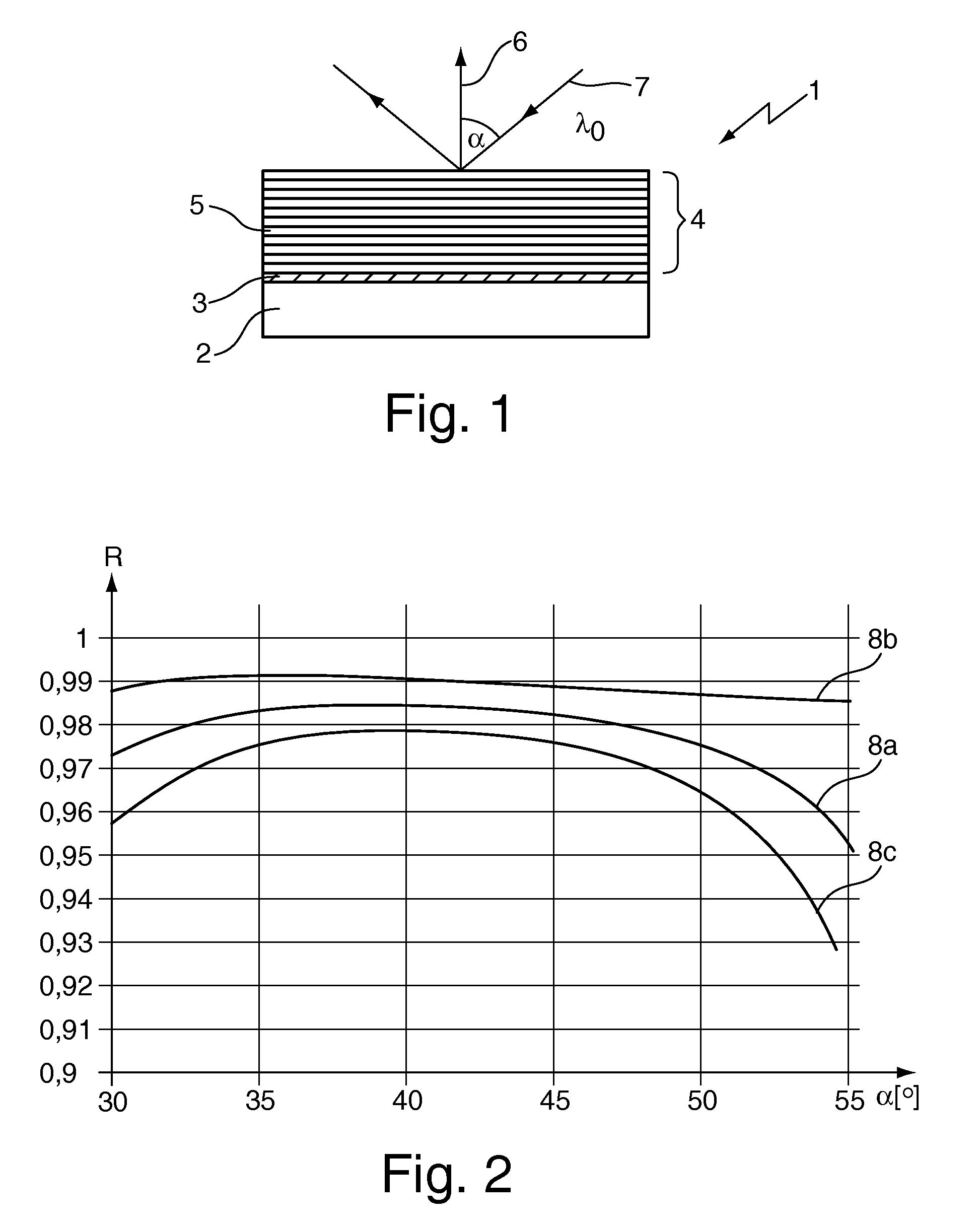
[0057]In FIG. 1 an optical element 1 is shown schematically having a substrate 2 of quartz glass, onto which a layer 3 of amorphous silicon has been deposited as a basic material. A multi-layer system 4 is arranged on the layer 3 comprising a plurality of single layers. The fifth single layer 5 as viewed from substrate 3 has been deposited here by ion beam sputtering generating an energy input of approx. 10 mJ / cm2 into single layer 5 in order to provide said single layer with a package density of more than 0.99. In the process the subjacent layer 3 consisting of silicon is heated. This heating, however, does not result in a noteworthy rearrangement of the atoms in the surface of silicon layer 3 due to the high melting point of silicon of approx. 1410° C. such that the said layer is not fused locally and has a roughness of less than 1 nm rms even though the single layer 5 and / or the multi-layer system 4 has been deposited.

[0058]Besides amorphous silicon, particularly crystalline sili...


PUM

PropertyMeasurementUnit
operating wavelengthaaaaaaaaaa
incident anglesaaaaaaaaaa
reflectivityaaaaaaaaaa

Abstract

An optical element (1a, 1b) for reflecting UV radiation at an operating wavelength below 250 nm, preferably at 193 nm, which has a substrate (2a, 2b), a reflective layer (3a, 3b) made of aluminum superimposed on the substrate (2a, 2b). The reflective aluminum layer (3a, 3b) is not transparent to UV radiation and is (111)-plane oriented. The reflective optical element (1a, 1b) has a reflectivity of more than 85%, preferably of more than 88%, and even more preferably of more than 92%, in a range of incident angles of at least 10°, preferably of at least 15°, at the operating wavelength. Also disclosed is an optical element having a reflective layer made from a material having a melting point higher than that of aluminum, as well as methods for producing such optical elements, and optical arrangements incorporating such optical elements.

Description

CROSS-REFERENCE TO RELATED APPLICATIONS[0001]This is a Continuation of International Application PCT / EP2008 / 009512, with an international filing date of Nov. 12, 2008, which was published under PCT Article 21(2) in English, and the complete disclosure of which is incorporated into this application by reference; the International Application, in turn, claims benefit of U.S. Provisional Application No. 60 / 987,969, filed Nov. 14, 2007, and of DE 10 2007 054 731.7-51, also filed Nov. 14, 2007, both of which are also incorporated into this Continuation by reference.FIELD OF AND BACKGROUND TO THE INVENTION[0002]The present invention relates to an optical element configured to reflect ultraviolet (UV) radiation at an operating wavelength below 250 nm, preferably at 193 nm, comprising: a substrate, and a reflective layer made of aluminum superimposed on the substrate, wherein the reflective aluminum layer is not transparent to the UV radiation. The invention also relates to an optical eleme...

Claims


Application Information

Patent Timeline
Patent Type & Authority Applications(United States)
IPC IPC(8): G03B27/54G02B5/30B05D5/06C23C14/34C23C14/35C23C16/513
CPCG02B5/0891G02B5/0833G03F7/70316G03F7/70958
Inventor PAZIDIS, ALEXANDRAZACZEK, CHRISTOPHFELDERMANN, HORSTHUBER, PETER
Owner CARL ZEISS SMT GMBH
Why Eureka
Try Eureka