
Method and apparatus for novel neutron activation geometries in a flowing carrier stream

a carrier stream and neutron activation geometrie technology, applied in the direction of material analysis, material analysis using wave/particle radiation, instruments, etc., can solve the problems of inability to apply neutron activation to atomic species in flowing streams, affecting the efficiency of neutron activation, and only limited control of incident radiation, so as to promote helical flow and lose energy yield

Inactive Publication Date: 2012-11-01
MURRAY ANDREW GERARD WILLIAM +1
View PDF3 Cites 4 Cited by
  • Summary
  • Abstract
  • Description
  • Claims
  • Application Information

AI Technical Summary

Benefits of technology

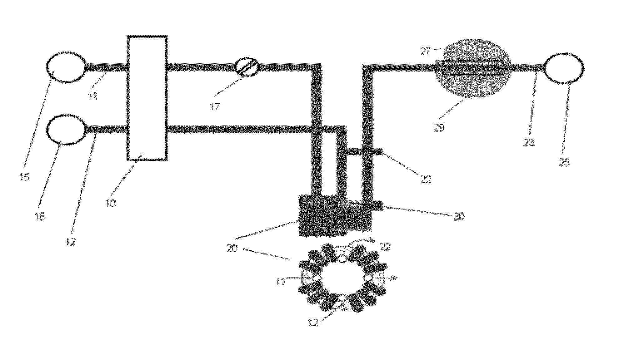
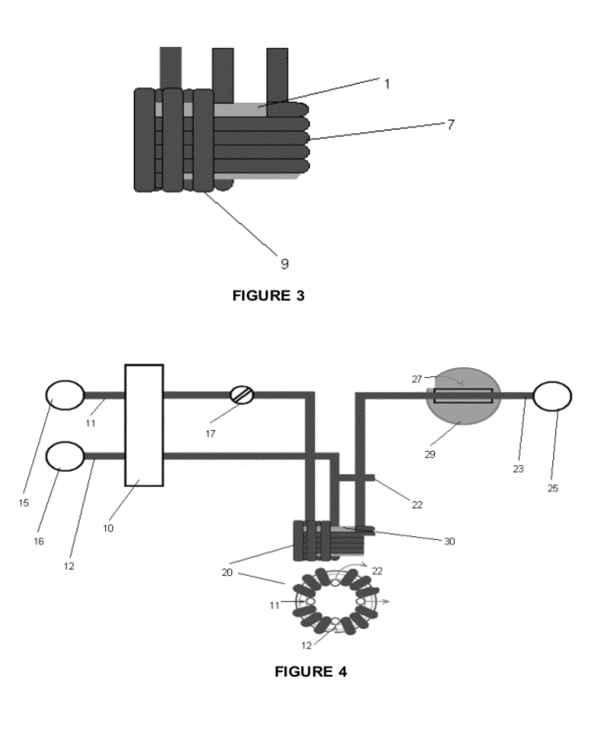
[0017]It is also an object of the present invention to provide an apparatus that permits control of the rate and direction of flowing fluid in the vicinity of a radiation source to optimise radiation of the fluid.
[0100]all components may be fabricated from medical grade plastics or glass thus permitting modifications to the system to be made relatively easily and at low cost;

Problems solved by technology

The neutron capture even after any immediate decay, often results in the formation of an unstable activation product.
However, neutron activation is more difficult to apply to atomic species in a flowing stream.
The use of a continuously flowing stream having a comparatively large cross section according to these prior art methods provided only limited control of the incident radiation.
Prior art systems and apparatus of this type are typically application specific, constructed for one purpose only, and cannot be adapted to other purposes.
However the conformations of each of these systems cannot be reconfigured for different targets and sources.
Furthermore, the configurations taught and disclosed in these patents impose significant limitations in regard to activation.
This limits the system to having a conduit that is sequentially looped around each of the source cores.
These systems, and other systems of the prior art such as the one described in US 2003 / 0007588 typically use narrow bore conduits and conduit loops, however these types of systems typically do not permit control of the rate or direction in which fluid sample can be passed through the conduits.
Furthermore they typically do not permit mixing between a carrier stream and the sample.

Method used


Image

  • Method and apparatus for novel neutron activation geometries in a flowing carrier stream
  • Method and apparatus for novel neutron activation geometries in a flowing carrier stream
  • Method and apparatus for novel neutron activation geometries in a flowing carrier stream

Examples


first embodiment

[0189]Two embodiments of the apparatus are possible depending on the reactant to be activated by the incident neutrons. For example, in a first embodiment the powdered magnesium can be activated off line by placing it in a glass tube, stoppering the tube ends and placing the sealed tube in close proximity to the neutron source. After activation, the glass tube is removed, the ends unstopped and activated column placed on line. The SIA (sequential injection analysis) valve is assembled, the reaction allowed to proceed by drawing methyl halide from Reservoir (15) and diethyl ether from Reservoir (16), allowing them to mix and react with the activated packed column magnesium powder and allowing the product to flow from the tail of the column into a pegboard flow cell.

second embodiment

[0190]In the apparatus, configuration Reservoir R1 is filled with methyl halide, Reservoir (16) is filled with diethyl ether. The sample conduit carries the methyl halide from Reservoir (15) into the activation thimble. The methyl halide is activated and flows to the head of a packed column containing powdered magnesium. A second conduit delivers diethyl ether to head of the packed column. The reaction proceeds over the length of the packed column and the product flows into the pegboard flow cell.

[0191]This approach can be used to provide reaction kinetic data for the formation of Grignards. The resulting organometallic halides can then be used as reactants in other chemical synthesis schemes depending on the half lives of the activated atomic species in the Grignard. A more complex apparatus can be built to pass the activated Grignard on for further reaction and possible kinetic rate elucidation.

Chemical Synthesis-Preparation of Activated Platinum Antineoplastics

[0192]The apparatus...


PUM


Abstract

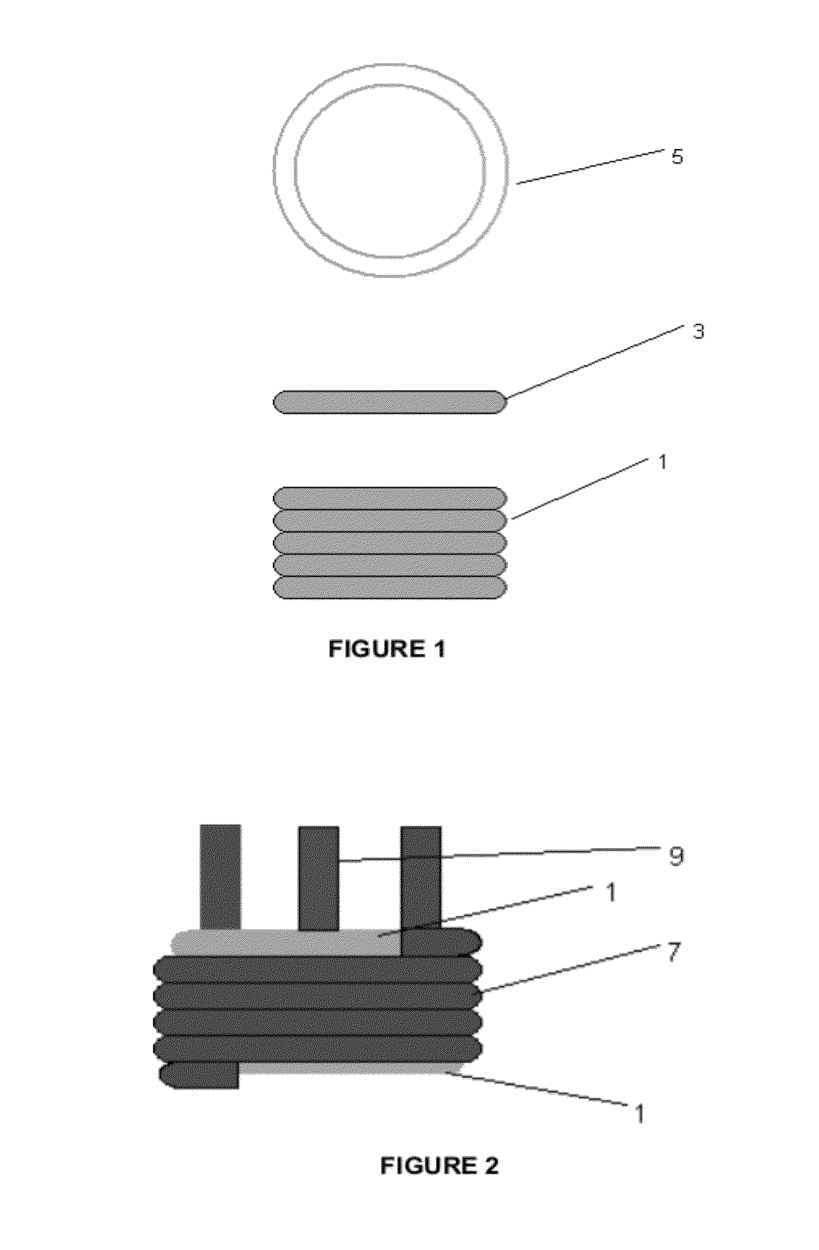
The present invention provides a nuclear activation apparatus for one or more fluid samples comprising the following modules;a means for introducing one or more fluid samples to a sample conduit,an activation thimble, comprising a section of sample conduit configured for multiple passes adjacent a radiation source,an absorber located adjacent to the activation thimble, anda detector located adjacent the sample conduit,wherein the relative arrangement of the modules can be altered specific to an application and the rate of flow of the fluid sample adjacent the radiation source can be controlled.

Description

FIELD OF INVENTION[0001]The present invention relates to the field of neutron activation of flowing streams, particularly neutron activation for detection of radio chemical decay.[0002]More particularly the method system and apparatus can be applied to conventional analytical determinations, basic chemical synthesis with activated reagents and chemical synthesis in vivo. In particular the latter may include chemical synthesis in isolated tissues where complex biological structures such as cells or cell organelles provide and participate in chemical interactions.[0003]In one particular aspect the present invention is suitable for use in chemical analysis and synthesis, including in vivo, in vitro and in vivo-in vitro.BACKGROUND ART[0004]It is to be appreciated that any discussion of documents, devices, acts or knowledge in this specification is included to explain the context of the present invention. Further, the discussion throughout this specification comes about due to the realis...

Claims


Application Information

Patent Timeline
Patent Type & Authority Applications(United States)
IPC IPC(8): G21G1/06G21C17/00
CPCG21G1/06G01N23/222
Inventor MURRAY, ANDREW GERARD WILLIAMBARTEL, ANTHONY GORDON
Owner MURRAY ANDREW GERARD WILLIAM
Learn More