
Method of Anion Production from Atoms and Molecules

a technology of anion and atom, which is applied in the direction of measuring devices, instruments, electric discharge tubes, etc., can solve the problems of reducing the comparability of analyzed samples with srm samples, reducing the accuracy of sputtering mechanisms, and providing high precision at the potential cost of degraded accuracy, etc., to achieve greater precision, increase ion intensity, and short time period

Inactive Publication Date: 2012-11-08
VOGEL JOHN
View PDF1 Cites 2 Cited by
  • Summary
  • Abstract
  • Description
  • Claims
  • Application Information

AI Technical Summary

Benefits of technology

[0026]Multiple applications of this ion source for elemental and isotopic analysis of material samples will be clear to anyone skilled in the art, but include: determination of relative isotopic and elemental abundances within isolated samples, chronometric analysis of samples containing natural radioactive isotopes, metrological quantification of element concentrations using isotope dilution methods, quantification of isotope-labeled molecular species within bioanalytic materials, and ion implantation of specific elemental or isotopic species.
[0027]It is an object of the present invention to provide an ion source for isotope ratio MS (IRMS) that produces an anion beam that reflects a sample's isotope and element abundance without mass bias within the portion of a sample being analyzed.
[0028]It is a further object of the present invention to provide an ion source for use with an absolute IRMS (AIRMS) that directly quantifies absolute abundances of both stable and radio-isotopes within a sample without normalization of the measurement to a separate sample of SRM.
[0029]It is another object of this invention to provide an ion source for IRMS and AIRMS analysis from which isotope dilution analyses can be performed over wide dynamic ranges in the isotope concentrations of diluent and sample without need of normalizing and calibrating SRMs.
[0030]It is yet another object of the present invention to increase the ion intensity obtained from isolated samples so that the rare isotopes within those samples may be quantified to greater precisions in shorter time periods.
[0031]It is also an object of the invention to allow selective ionization of neutral sputtered atoms by adjusting the excited state of the sample atom, the ionizing atom, or both using specific wavelengths of light to enhance ionization of the desired element while suppressing ionization of other sputtered components.

Problems solved by technology

High intensity ion beams arise from sputter sources through the rapid erosion of the sample surface, which reduces the comparability of the analyzed samples with the SRM samples, providing high precision at the potential cost of degraded accuracy.
The sputtering mechanism itself cannot have a mass bias because multiple monolayers are displaced from the sample every second, promoting rapid equilibration between the bulk material and the sputtered atoms.
The mechanism that created and sustained the apparent ionization within a glowing volume produced ions efficiently with low mass bias as the sample surface sputtered and pitted but was not understood and, hence, not reproducible.

Method used


Image

  • Method of Anion Production from Atoms and Molecules
  • Method of Anion Production from Atoms and Molecules
  • Method of Anion Production from Atoms and Molecules

Examples


Embodiment Construction

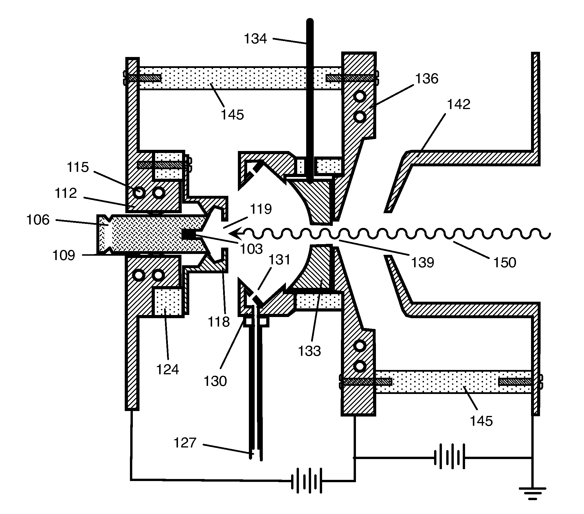
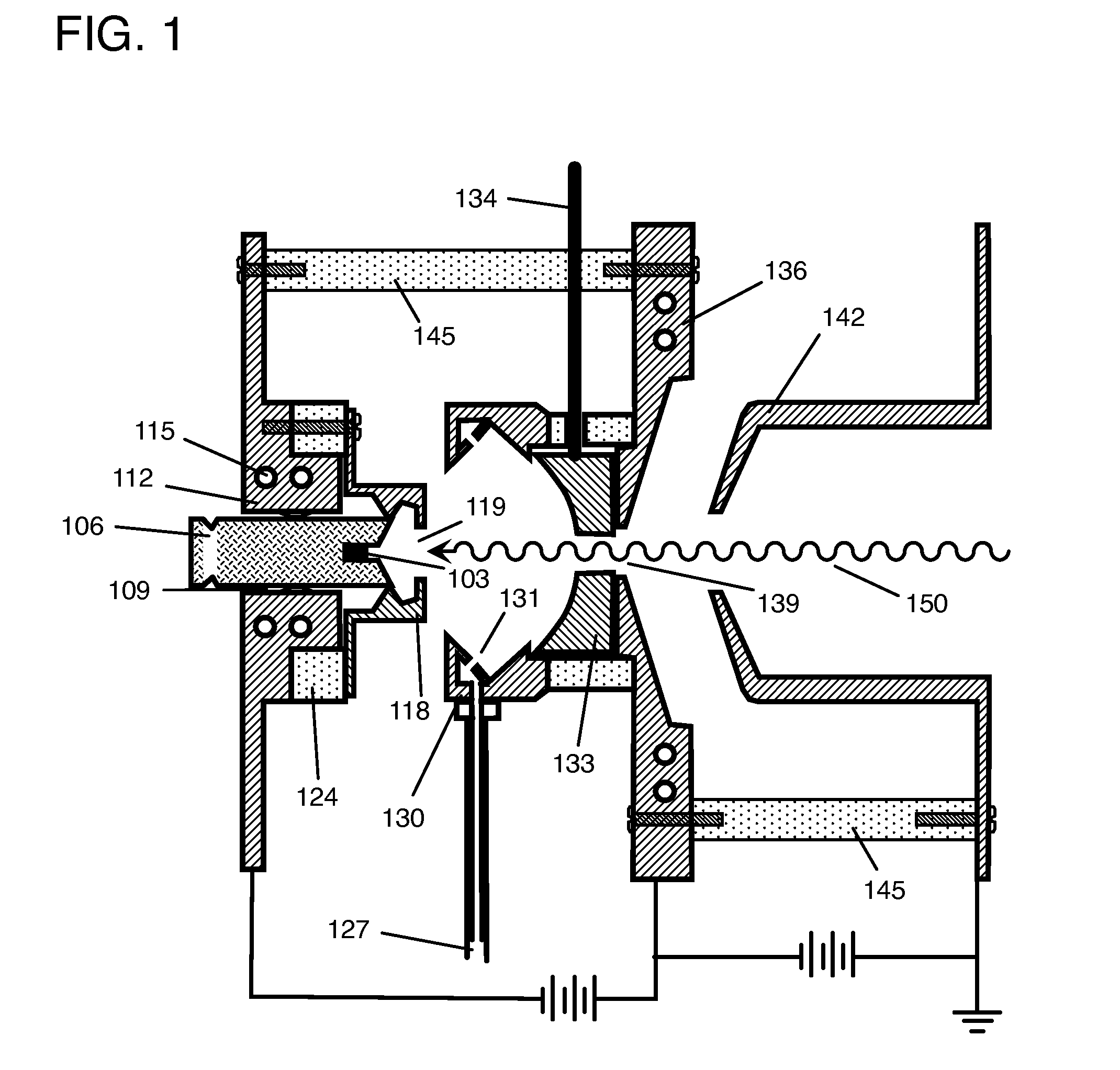
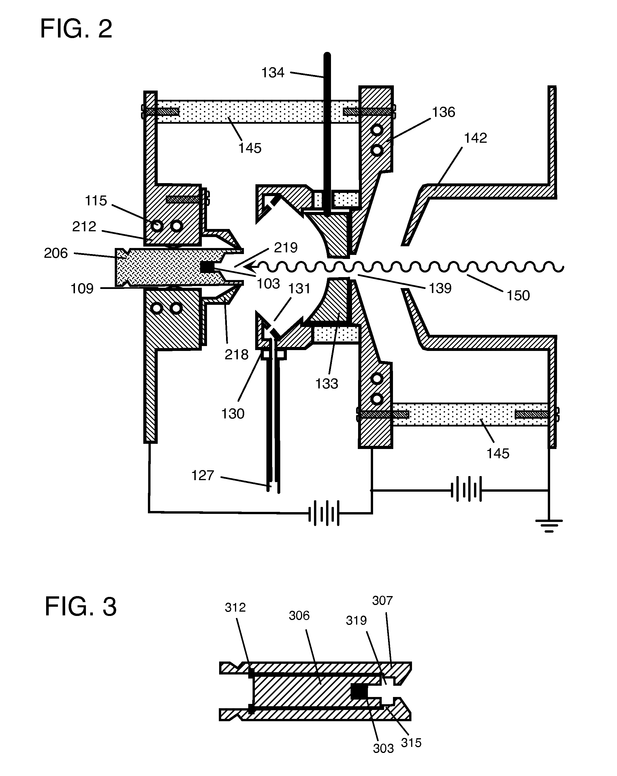
[0040]Referring to FIGS. 1 through 5, wherein like numbers refer to similar parts, the invention is described. The Figures show only schematic representations of a sputter ion source and are illustrative only. Those skilled in the art will recognize the relation between the described components in the Figures and the specific components in particular realizations of a sputter ion source. Components required for an understanding of the invention and its application are represented in the Figures, and those skilled in the art recognize how these components are typically arranged within evacuated volumes and supplied with electrical currents and potentials from power supplies, cooling water from circulation pumps, metal vapor from a boiler, and gases from a pressurized cylinder or other storage. Cs is the most common metal vapor used in these sputter ion sources and is referred to here as only representative of the potential sputtering primary ions that may include the alkali and alkal...


PUM


Abstract

Ion sources are described for producing negative ion beams with low mass bias in which a neutral vapor of an electropositive element ionizes neutral atoms or molecules.

Description

CROSS REFERENCE TO RELATED APPLICATIONS[0001]This patent application relates to, and claims the priority benefit from, U.S. Provisional Patent Application Ser. No. 61 / 451,094 filed on Mar. 9, 2011, which is incorporated herein by reference in its entiretySTATEMENT REGARDING FEDERAL SPONSORSHIP[0002]Not Applicable.REFERENCE TO LISTING, TABLE, OR APPENDIX[0003]Not Applicable.FIELD OF INVENTION[0004]Anion production, atomic mass spectrometry, isotope ratio mass spectrometry, accelerator mass spectrometry, isotope ratio chronology, isotope-labeled molecular tracing, isotope quantitation, ion implantation.BACKGROUND OF THE INVENTION[0005]The invention relates to the design and methods of operation for sources of energetic atomic anions (negative ions). These anions have exemplary use for direct quantification of isotopic and elemental abundance ratios in isolated samples using mass spectrometry. The invention uses charge exchange between neutral atoms and molecules to create atomic and m...

Claims


Application Information

Patent Timeline
Patent Type & Authority Applications(United States)
IPC IPC(8): H01J27/20
CPCH01J27/028H01J27/20H01J2237/31701H01J2237/061H01J2237/0815H01J37/08
Inventor VOGEL, JOHN
Owner VOGEL JOHN
Learn More