
Power transmission train

a technology of transmission train and power transmission, which is applied in the direction of electric energy vehicles, propulsion using engine-driven generators, locomotives, etc., can solve the problems of further cost saving, and achieve the effects of more space saving, more cost-effective, and more lightweigh

Inactive Publication Date: 2012-11-08
SAMSUNG SDI BATTERY SYST
View PDF22 Cites 6 Cited by
  • Summary
  • Abstract
  • Description
  • Claims
  • Application Information

AI Technical Summary

Benefits of technology

[0005]An objective of the invention is to create a power transmission train for a range extender module which is more cost-effective, more lightweight and more space-saving than the known designs, in particular in order to allow it to be used in small city vehicles.
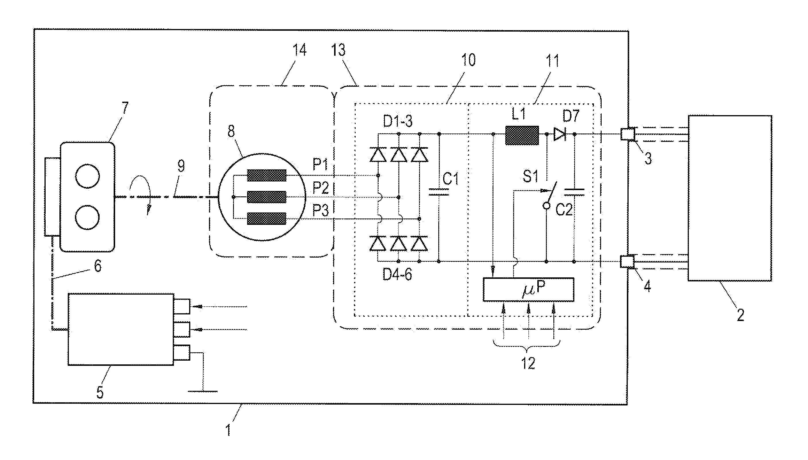
[0007]The invention is based on the surprising finding that considerable costs, weight and installation space can be saved when the power transmission train is designed exclusively in a unidirectional manner, that is to say comprising the unidirectional sequence of starter motor→internal combustion engine→AC generator→rectifier→DC / DC converter, even if it requires a dedicated starter motor: a costly bidirectional inverter can be dispensed with. Since the inverter and generator do not have to be dimensioned for the high starting current of an internal combustion engine, considerable installation space and weight can be saved. In addition, a simple passive rectifier is sufficient, and the separate starter motor for the internal combustion engine is a commercially available, cost-effective part. Furthermore, the angular position sensor in the generator is also dispensed with, this saving further costs.
[0009]The AC generator is preferably a three-phase permanent-magnet synchronous machine (PSM) which is distinguished. by a particularly simple and robust design.
[0013]A further advantageous embodiment of the invention is distinguished in that the internal combustion engine and / or the AC generator have / has a liquid cooling system which also cools the rectifier and / or the DC / DC converter. As a result, further components and therefore installation space, weight and costs can be saved.
[0014]It is particularly advantageous when the rectifier and the DC / DC converter are integrated in the housing of the AC generator or are flange-connected to said housing of the AC generator in order to create an autonomous unit.

Problems solved by technology

Furthermore, the angular position sensor in the generator is also dispensed with, this saving further costs.

Method used


Image

  • Power transmission train
  • Power transmission train

Examples


Embodiment Construction

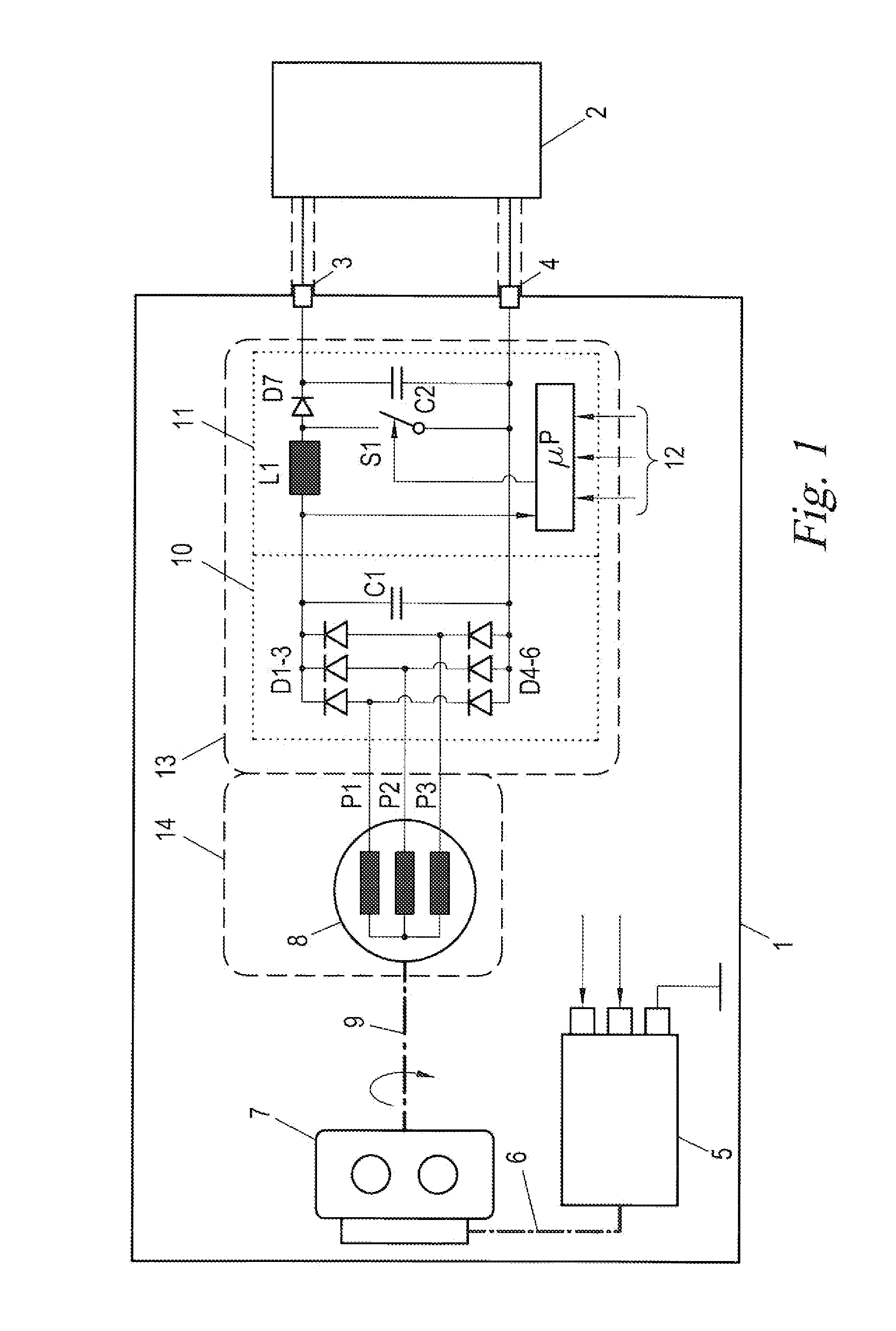
[0018]FIG. 1 illustrates a range extender module 1 which feeds a high-voltage battery 2 for an electric traction drive (not shown further) of a hybrid vehicle. The range extender module 1 is, as an autonomous, modularly exchangeable unit, arranged, for example, in a housing or on an assembly support and is equipped with electrical connections 3, 4 for connection to the high-voltage battery 2.

[0019]The range extender module 1 contains a unidirectional power transmission train which includes, in succession, the following.

[0020]A starter motor 5, as is commercially available, for example, as a standard 12-volt starter motor for motor vehicles. A low- to medium-power internal combustion engine 7 which can be started by the starter motor 5 by means of, for example, a belt drive or a pinion 6, for example, in the range of 15 to 30 kW. The internal combustion engine 7 is preferably controlled by a control device (not illustrated) which can communicate with the rest of the vehicle via a sui...


PUM


Abstract

A power transmission train for a range extender module, including an internal combustion engine, an AC generator which is mechanically driven by the internal combustion engine, and a rectifier which is electrically connected to the AC generator and has a unidirectional DC / DC converter connected downstream for the purpose of feeding an electrical load, with the internal combustion engine being equipped with its own electric starter motor.

Description

CROSS-REFERENCE TO RELATED APPLICATIONS[0001]The present application is a National Stage Application of PCT International Application No. PCT / EP2010 / 070298 (filed on Dec. 20, 2010), under 35 U.S.C. §371, which claims priority to German Patent Application No. 10 2010 004 709.0 (filed on Jan. 15, 2010). which are each hereby incorporated by reference in their respective entireties.FIELD OF THE INVENTION[0002]The invention relates to a power transmission train for a range extender module.BACKGROUND OF THE INVENTION[0003]Assemblies which extend the range of the vehicle beyond the purely electric range are intended to be employed in future drives for electric vehicles. To this end, so-called range extender modules which contain a small internal combustion engine which drives-a mechanically coupled generator for generating auxiliary and / or emergency power are under discussion. In this case. the internal combustion engine is operated continuously at its optimum operating point, as a result...

Claims


Application Information

Patent Timeline
IPC IPC(8): B60L11/12B60L50/15
CPCB60K6/46B60L11/123B60L11/126Y02T10/7216Y02T10/6217Y02T10/7077B60L2210/10B60L50/61B60L50/62Y02T10/62Y02T10/70Y02T10/72Y02T10/7072
Inventor BOUVIER, STEPHANLANZENBERGER, HEINZSCHMIDHOFER, ANDREAS
Owner SAMSUNG SDI BATTERY SYST
Learn More