Phase controller

a phase controller and controller technology, applied in the field of phase controllers, can solve the problems of large-scale facilities for bringing an ultra-high vacuum state, and achieve the effects of simple vacuum pump, increased refractive index, and increased magnetic scattering

Inactive Publication Date: 2012-11-08
SAITAMA MEDICAL UNIVERSITY
View PDF1 Cites 11 Cited by
  • Summary
  • Abstract
  • Description
  • Claims
  • Application Information

AI Technical Summary

Benefits of technology

[0011]According to the present invention constituted as described above, the soft X-ray has an energy in a wavelength which is close to the core level absorption edge of the transition metal forming the reflection surface. When the soft X-ray incident on the vacuum vessel is to be reflected by the reflection surface, therefore, magnetic scattering caused by the magnetic field applied in the position of the reflection surface is increased by a resonant effect of a magnetic circular dichroism. In other words, although a difference is made in a refractive index between circularly polarized counterclockwise light and circularly polarized clockwise light in the core level absorption edge causing the magnetic scattering, the difference in the refractive index leads to a phase difference between the circularly polarized counterclockwise light and the circularly polarized clockwise light. By varying the number of the reflection surfaces, a strength of the magnetic field or an angle of incidence, it is possible to control the phase difference. Moreover, the difference in the refractive index is increased by the resonant effect of the magnetic circular dichroism. Therefore, it is possible to obtain, at a t

Problems solved by technology

However, this method has a problem in that large-scale facilities referred to as a so-called synchrotron (synchronous circular accelerator) or linac (linear acc

Method used


Image

  • Phase controller
  • Phase controller
  • Phase controller

Examples


first embodiment

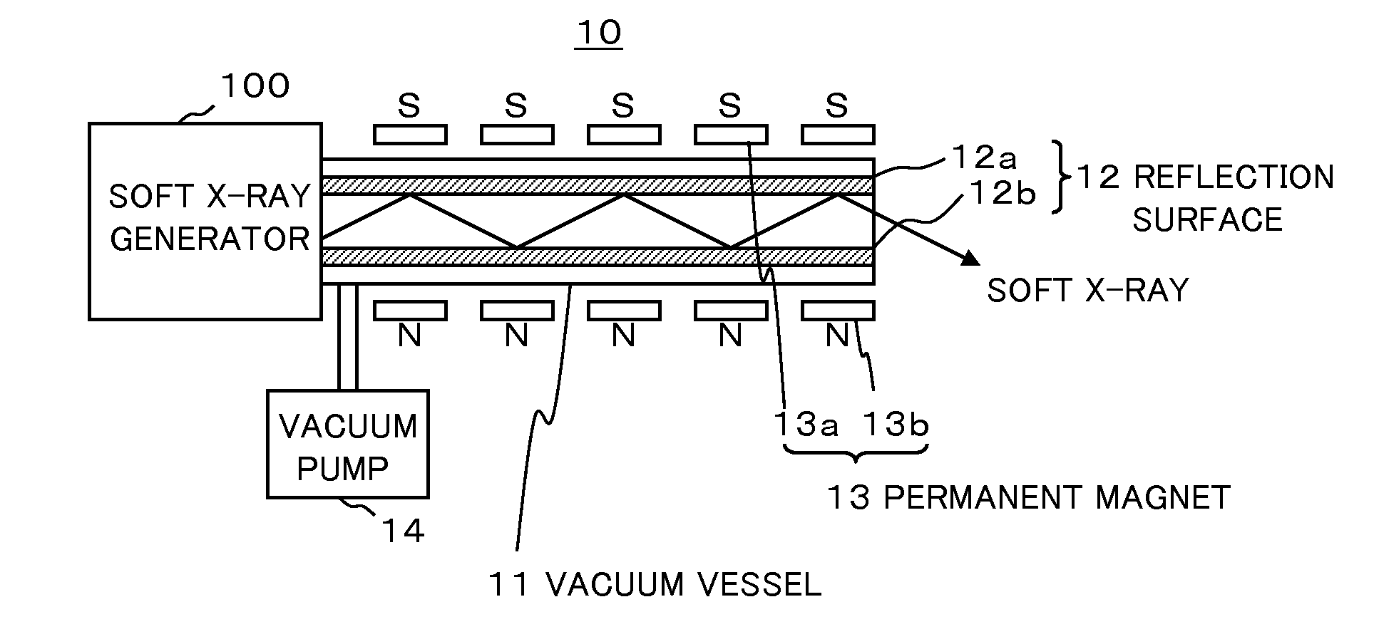
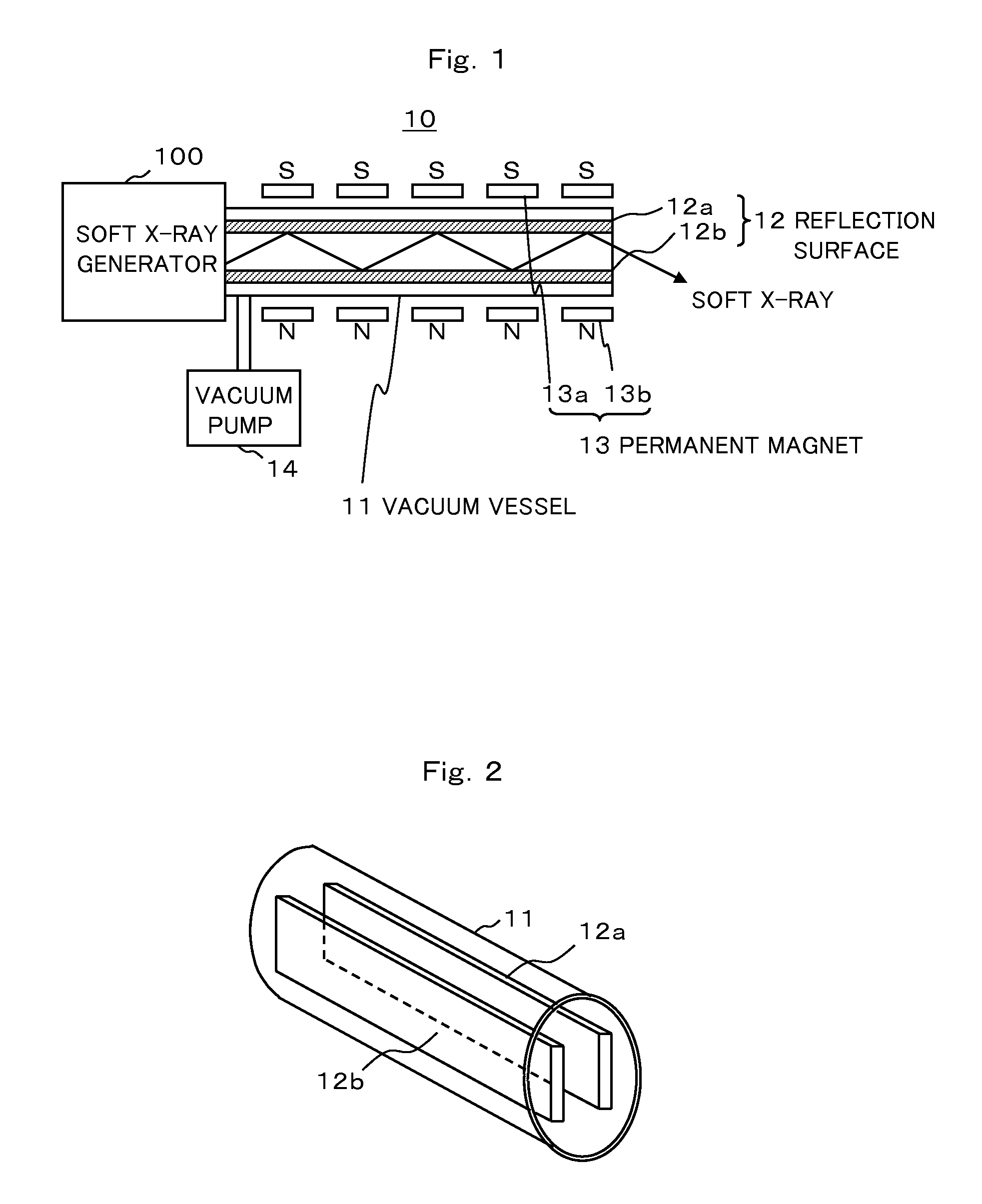
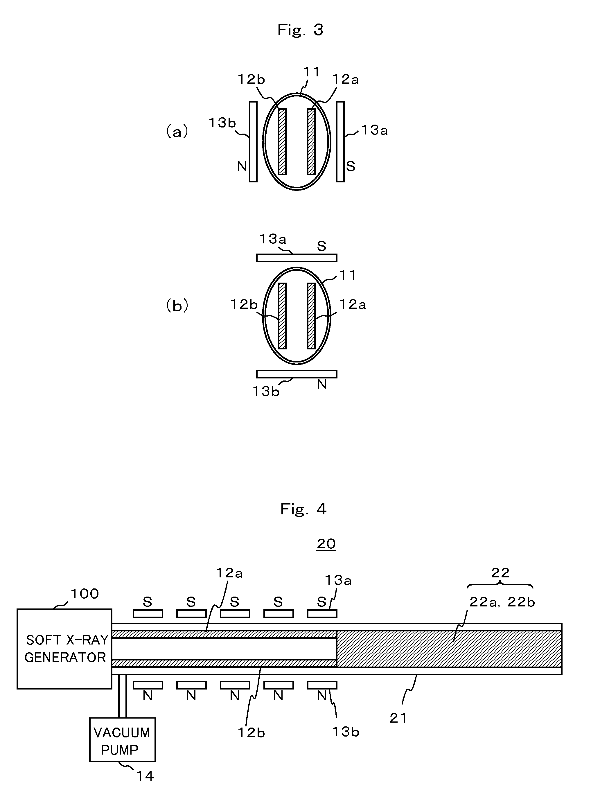
[0017]An embodiment of a phase controller according to the present invention will be described below with reference to the drawings. FIG. 1 is a view showing an example of a structure of a circularly polarized light converter carrying out a phase controller according to a first embodiment. FIG. 2 is a view showing an example of an arrangement of a reflection surface according to the first embodiment. FIG. 3 is a view showing an example of an arrangement of a permanent magnet according to the first embodiment.

[0018]As shown in FIG. 1, a circularly polarized light converter 10 according to the first embodiment includes a hollow vacuum vessel 11 serving as a route for a soft X-ray which is emitted from a soft X-ray generator 100, a reflection surface 12 formed on an inside of the vacuum vessel 11, a permanent magnet 13 for generating a magnetic field, and a vacuum pump 14 for bringing a vacuum state in the vacuum vessel 11.

[0019]As shown in FIG. 2, for example, the vacuum vessel 11 is ...

second embodiment

[0027]Next, a second embodiment according to the present invention will be described with reference to the drawings. FIG. 4 is a view showing an example of a structure of a circularly polarized light converter carrying out a phase controller according to the second embodiment. In FIG. 4, components having the same reference numerals as those shown in FIG. 1 have the same functions and repetitive description will be omitted.

[0028]As shown in FIG. 4, a circularly polarized light converter 20 according to the second embodiment includes a second reflection surface 22 in addition to the structure illustrated in FIG. 1. Moreover, a vacuum vessel 21 has a double length in the longitudinal direction as compared with the vacuum vessel 11 shown in FIG. 1.

[0029]The second reflection surface 22 is disposed in a subsequent part to a reflection surface 12 at an inside of the vacuum vessel 21. A length of the second reflection surface 22 is equal to that of the reflection surface 12. In the same m...


PUM


Abstract

A reflection surface 12 constituted by a transition metal having a core level absorption edge in the vicinity of a wavelength of a soft X-ray is formed on an inside of a vacuum vessel 14, and furthermore, there is provided a permanent magnet 13 for generating a magnetic field in a perpendicular direction to a longitudinal direction of the vacuum vessel 14 in a position of the reflection surface 12 by which the soft X-ray is to be reflected, and the soft X-ray to be linearly polarized light incident on the vacuum vessel 14 is reflected at plural times over the reflection surface 12 in a position where the magnetic field is applied in such a manner that magnetic scattering is increased by a resonant effect of a magnetic circular dichroism when the soft X-ray is reflected by the reflection surface 12. Thus, a great difference in a refractive index is made between circularly polarized counterclockwise light and circularly polarized clockwise light which constitute the linearly polarized light, and a phase difference between the circularly polarized counterclockwise light and the circularly polarized clockwise light is obtained at a time. Consequently, it is possible to reversibly convert the soft X-ray from the linearly polarized light into the circularly polarized light or from the circularly polarized light into the linearly polarized light by a reflection to be carried out at only several times.

Description

TECHNICAL FIELD[0001]The present invention relates to a phase controller which is suitably used for a device serving to convert light having a high energy such as a soft X-ray from linearly polarized light to circularly polarized light, for example.BACKGROUND ART[0002]Conventionally, there is provided a device for converting light from linearly polarized light to circularly polarized light. For example, a simple structure such as a transmission type polarizing plate or polarizing film is used for converting visible light or infrared light into circularly polarized light. Moreover, there is also provided an undulator for spirally meandering an electron beam to carry out a conversion into circularly polarized light by periodically applying a magnetic field in a horizontal or perpendicular direction with respect to an orbit of the electron beam (for example, see Patent Documents 1 and 2).[0003]Patent Document 1: Japanese Laid-Open Patent Publication No. 7-288200[0004]Patent Document 2:...

Claims


Application Information

Patent Timeline
IPC IPC(8): G21K1/16
CPCG21K1/06
Inventor KURODA, HIROTOBABA, MOTOYOSHIYONEYA, SHIN
Owner SAITAMA MEDICAL UNIVERSITY
Why Eureka
Try Eureka