Method and Device for Monitoring a High-Pressure Fuel System

Inactive Publication Date: 2012-11-08
ROBERT BOSCH GMBH
View PDF8 Cites 6 Cited by
  • Summary
  • Abstract
  • Description
  • Claims
  • Application Information

AI Technical Summary

Benefits of technology

[0013]According to one refinement, a calibration fuel injection is also executed, this calibration fuel injection occurring earlier than the first fuel injection by a calibration time interval. The calibration time interval is longer than the decay time of a pressure wave triggerable by the calibration fuel injection in the fuel injection system. This means that the first fuel injection and thus also the second fuel injection which occurs later are not influenced by the pressure wave of the calibration fuel injection. In additional steps, a calibration fuel injection quantity injected via the calibration fuel injection is ascertained, and a triggering time for the first and/or the second fuel injection is determined, based on the calibration fuel injection quantity and the setpoint fuel injection quantity. The injection quantity of the first fuel injection and thus its effect on the second fuel injection quantity may be monitored in a particularly precise manner in this way, enabling the detection of already minor deviations between the actual fuel pressure and the setpoint fuel pressure.
[0014]The calibration fuel injection and ascertainment of the calibration fue

Problems solved by technology

The signal supplied by the pressure sensor may be faulty due to damage, targeted manipulation, e.g., in the context of engine tuning or because of a pronounced drift, which results in the actual pressure prevailing in the fuel pressure storage device deviating more than intended from the setpoint pressure.
The service life of components of the fuel system may be reduced in this way, the mixture-forming quality may decline and there may be deviations in the actual injection quantity from a setpoint injection quanti

Method used


Image

  • Method and Device for Monitoring a High-Pressure Fuel System
  • Method and Device for Monitoring a High-Pressure Fuel System
  • Method and Device for Monitoring a High-Pressure Fuel System

Examples


Example

[0022]In the figures, the same reference numerals are used to denote the same components or those having the same function, as long as nothing to the contrary is indicated.

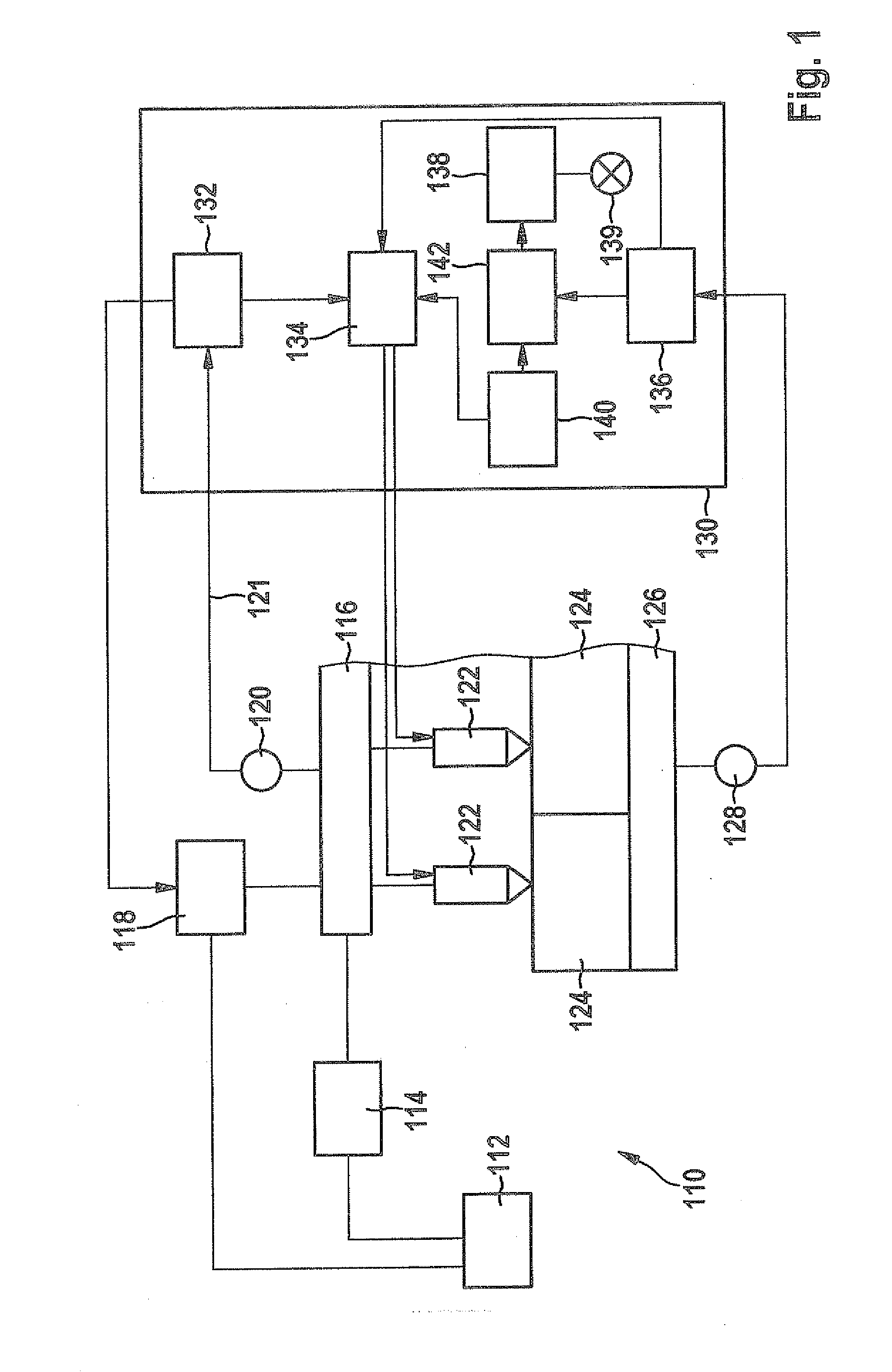
[0023]A fuel system of an internal combustion engine in FIG. 1 is labeled with reference numeral 110 on the whole. It includes a fuel tank 112, from which a delivery device 114, for example, including a predelivery pump and a high-pressure pump, delivers fuel to a fuel pressure storage device 116. A pressure regulating valve 118 and a pressure sensor 120 are connected to this fuel pressure storage device and multiple injection devices (injectors) 122, which inject fuel directly into combustion chambers 124 of the internal combustion engine (not otherwise shown) assigned to them. Combustion of the injected fuel in combustion chambers 124 causes crankshaft 126 to rotate. A crankshaft sensor 128 detects the revolutions and the rotational speed of crankshaft 126.

[0024]Operation of the internal combustion engine and fu...


PUM


Abstract

A method for monitoring a fuel pressure in a fuel injection system of an internal combustion engine. A setpoint fuel pressure is initially set in the fuel injection system. Next, a first fuel injection and a subsequent second fuel injection are executed at a time interval shorter than a decay time of a pressure wave in the fuel injection system, triggerable by the first fuel injection. In an additional step, a monitored fuel injection quantity, which is injected via the second fuel injection, is ascertained. An action is executed if the monitored fuel injection quantity differs from a setpoint fuel injection quantity, which is predefinable for the setpoint fuel pressure, by more than a limiting value. The invention also relates to a computer program product for executing the method and to a device for monitoring a fuel pressure in a fuel injection system of an internal combustion engine.

Description

FIELD OF THE INVENTION[0001]The present invention relates to a method for monitoring a fuel pressure in a fuel injection system of an internal combustion engine. Furthermore, the present invention relates to a computer program product for executing such a method and a device for monitoring a fuel pressure in a fuel injection system of an internal combustion engine.BACKGROUND INFORMATION[0002]Common rail fuel systems in which fuel is delivered by a delivery device into a fuel pressure storage device, the so-called rail, are believed to be available from the market. Multiple fuel injectors, which inject fuel directly into the assigned combustion chambers, are connected to the fuel pressure storage device. The pressure in the fuel pressure storage device is detected by a pressure sensor and regulated by a setting device to a variable setpoint pressure. The fuel injection quantity injected into a combustion chamber of the internal combustion engine depends, on the one hand, on the actua...

Claims


Application Information

Patent Timeline
IPC IPC(8): F02D41/32F02D41/26
CPCF02D41/22F02D41/222F02D41/402Y02T10/44F02D2041/224F02D2041/228F02D2250/04F02D2041/223Y02T10/40
Inventor TOPP, STEPHANPECK, RAINERZIEHER, RENEKRIECHBAUM, CHRISTIANMEYER-SALFELD, STEFFEN
Owner ROBERT BOSCH GMBH
Why Eureka
Try Eureka