Method and device for error-compensated current measurement of an electrical accumulator

a technology of error-compensated current and electrical accumulator, which is applied in the direction of measurement devices, electrical measurements, instruments, etc., can solve the problems of additive errors, and achieve the effects of high manufacturing tolerance, high measuring accuracy, and high manufacturing toleran

Inactive Publication Date: 2012-11-08
ROBERT BOSCH GMBH
View PDF9 Cites 24 Cited by
  • Summary
  • Abstract
  • Description
  • Claims
  • Application Information

AI Technical Summary

Benefits of technology

[0005]The exemplary embodiments and / or exemplary methods of the present invention are intended to allow the use of inexpensive components, for example having high manufacturing tolerances, without resulting in a high measuring error. In particular, the exemplary embodiments and / or exemplary methods of the present invention are intended to allow high measuring accuracies to be achieved without the need for individual calibrations of individual circuits, for example to compensate for manufacturing tolerances. In particular, the current measurement according to the present invention allows a considerable increase in the accuracy of state of charge estimations which relate to the accumulator. Such estimations are based, among other things, on a current measurement with the aid of a shunt, the current values being integrated, which results in additive errors. Such state of charge estimations, also referred to as SOC estimations, are necessary in particular for ascertaining the remaining range of motor vehicles in which an electrical accumulator provides (at least part of) the traction power.

Problems solved by technology

Such estimations are based, among other things, on a current measurement with the aid of a shunt, the current values being integrated, which results in additive errors.

Method used


Image

  • Method and device for error-compensated current measurement of an electrical accumulator
  • Method and device for error-compensated current measurement of an electrical accumulator
  • Method and device for error-compensated current measurement of an electrical accumulator

Examples


Embodiment Construction

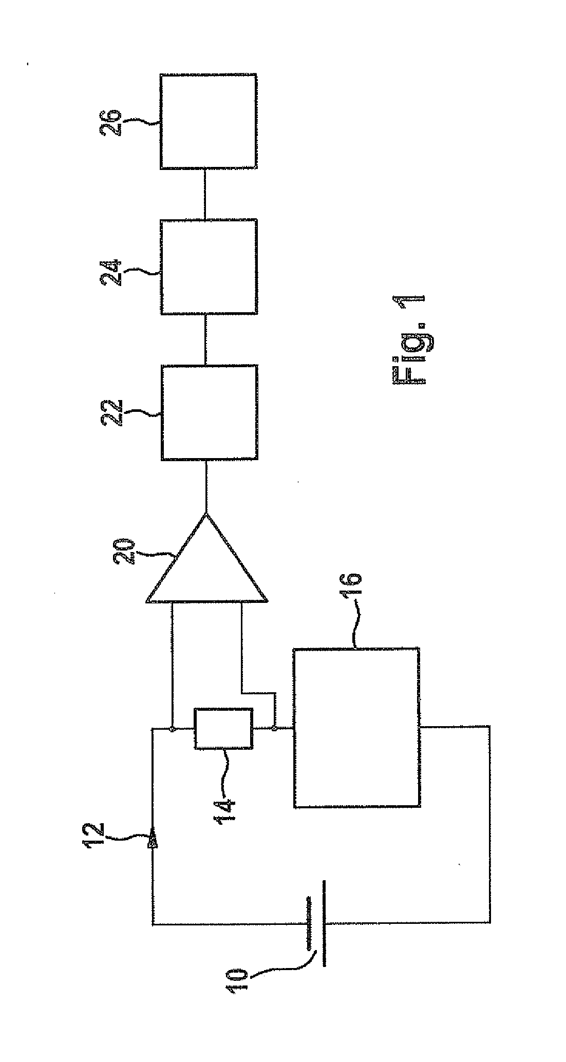
[0051]FIG. 1 shows an accumulator 10, which generates current 12 which flows through a shunt resistor 14 and a consumer 16. Accumulator 10, shunt resistor 12, and consumer 16 form a closed circuit. Instead of shunt resistor 10, a continuous line may be used, a Hall sensor or some other magnetic sensor detecting the magnetic field generated by current 12 and deducing current 12 therefrom. The dropping voltage at the shunt resistor 14 is supplied to a buffer circuit 20, which has a high internal resistance and optionally amplifies the voltage signal. The output of the buffer circuit is connected to a sample-and-hold stage 22, which samples and holds the analog value supplied by buffer circuit 20, and relays same to an A / D converter 24, which generates a digital value from the analog signal and supplies the digital value to microcontroller 26 for further processing. Elements 20, 22, 24 and optionally also 26 are elements of a signal preprocessing circuit, each of which introduces error...


PUM


Abstract

A method for error-compensated current measurement of an electrical accumulator, including: providing a time window-related estimated charge ascertained by a model-based estimator from operating variables of the accumulator and reflecting the estimated charge that has been withdrawn from the accumulator and supplied to the accumulator within the time window; and detecting the accumulator current supplied to the accumulator and withdrawn from the accumulator during the time window, with a current detection sensor. A zero crossing point in time (estimated charge is essentially zero) and a maximum point in time (the absolute value of the estimated charge essentially has a relative maximum or has a value which is greater than a minimum charge difference) are detected. A current measurement offset error is ascertained at the zero crossing point in time by comparing the estimated charge to the detected accumulator current. The accumulator current is ascertained according to the current measurement offset error, and a current measurement scaling error is ascertained at the maximum point in time by comparing the estimated charge to the detected accumulator current. The ascertained current measurement offset error is subtracted from the comparison result thus obtained, and the accumulator current is compensated for based on the current measurement scaling error. A related device for error-compensated current measurement is also described.

Description

FIELD OF THE INVENTION[0001]The present invention is directed to a method for compensating for errors in current measurements, in particular current measurements for ascertaining a state of charge of an electrical accumulator which is used as a store for traction power of a motor vehicle.BACKGROUND INFORMATION[0002]For measuring current, current sensors, for example so-called shunt resistors, through which the current to be measured flows, or magnetic sensors for detecting the magnetic field generated by the current, are used. Based on the drop in voltage, the current which flows through may be deduced with the aid of the resistance value. The dropping voltage at the shunt resistor is preprocessed by (high-impedance) measuring amplifiers or buffer stages, and in the case of digital further processing is transmitted to an analog / digital converter. The analog / digital converter uses a voltage reference for the conversion.[0003]In particular changes in temperature, as well as other infl...

Claims


Application Information

Patent Timeline
Patent Type & Authority Applications(United States)
IPC IPC(8): G01R19/32
CPCG01R19/0092G01R35/005G01R31/3651G01R31/361G01R31/367G01R31/3828
Inventor BOEHM, ANDRE
Owner ROBERT BOSCH GMBH
Why Eureka
Try Eureka