[0017]The present invention discloses, in at least certain aspects, a light-weight high-strength multi-component pipe that can be installed as a stand-alone pipe restoring a host pipeline to (or near) its original performance parameters and original service life, while providing increased internal and external
corrosion protection and increased protection from damage, e.g. during earthquakes, accidents, and acts of terrorism. In certain aspects, a “stand-alone” pipe as used herein is a pipe that withstands all (or substantially all) installation and operational loads without assistance.
[0018]In certain aspects, the present invention discloses a stand-alone
reinforced thermoplastic pipe of continuous length with: a layer of polymeric material; two or more
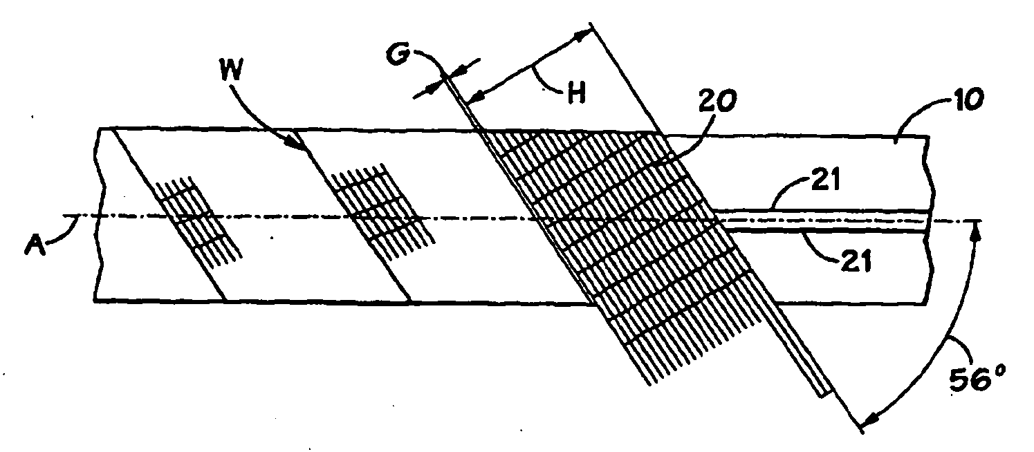
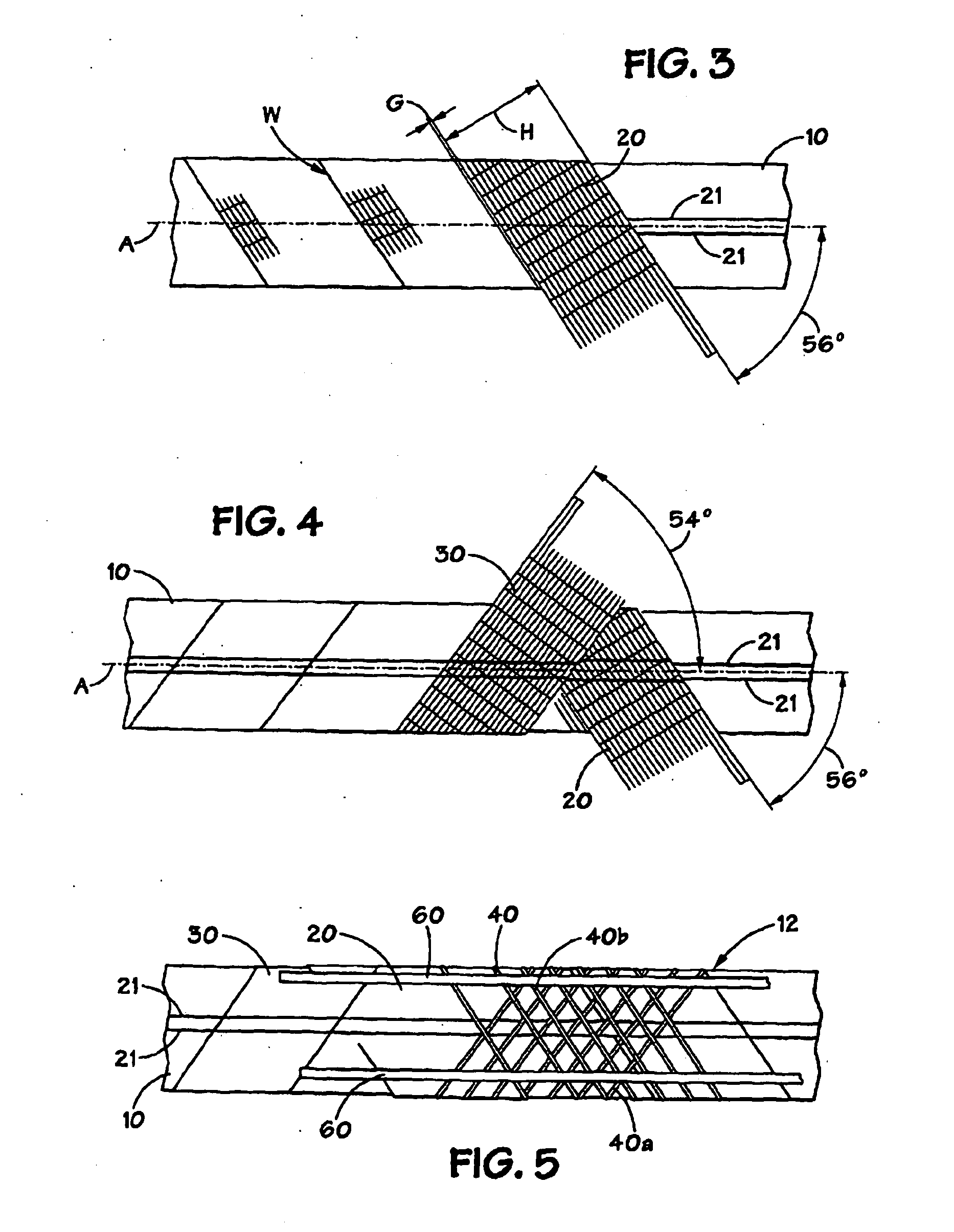
layers of fabric reinforcement material; optionally, an axial strengthener [e.g. axial tapes (in one aspect,
fiber tapes) or
socks, or flattened tubes, e.g., in certain aspects, made from carbon
fiber based material, or any suitable high strength
fiber or material disclosed herein] for increasing strength; orbitally wound fibers to lock the tapes in relationship to the fabric reinforcement; optionally, one or a series of fiber optic cables; and, optionally such cables covered by a protective layer, e.g. a protective
polymer layer, which, in certain aspects mitigates installation damage and provides structure for collecting and removing permeated fluids.
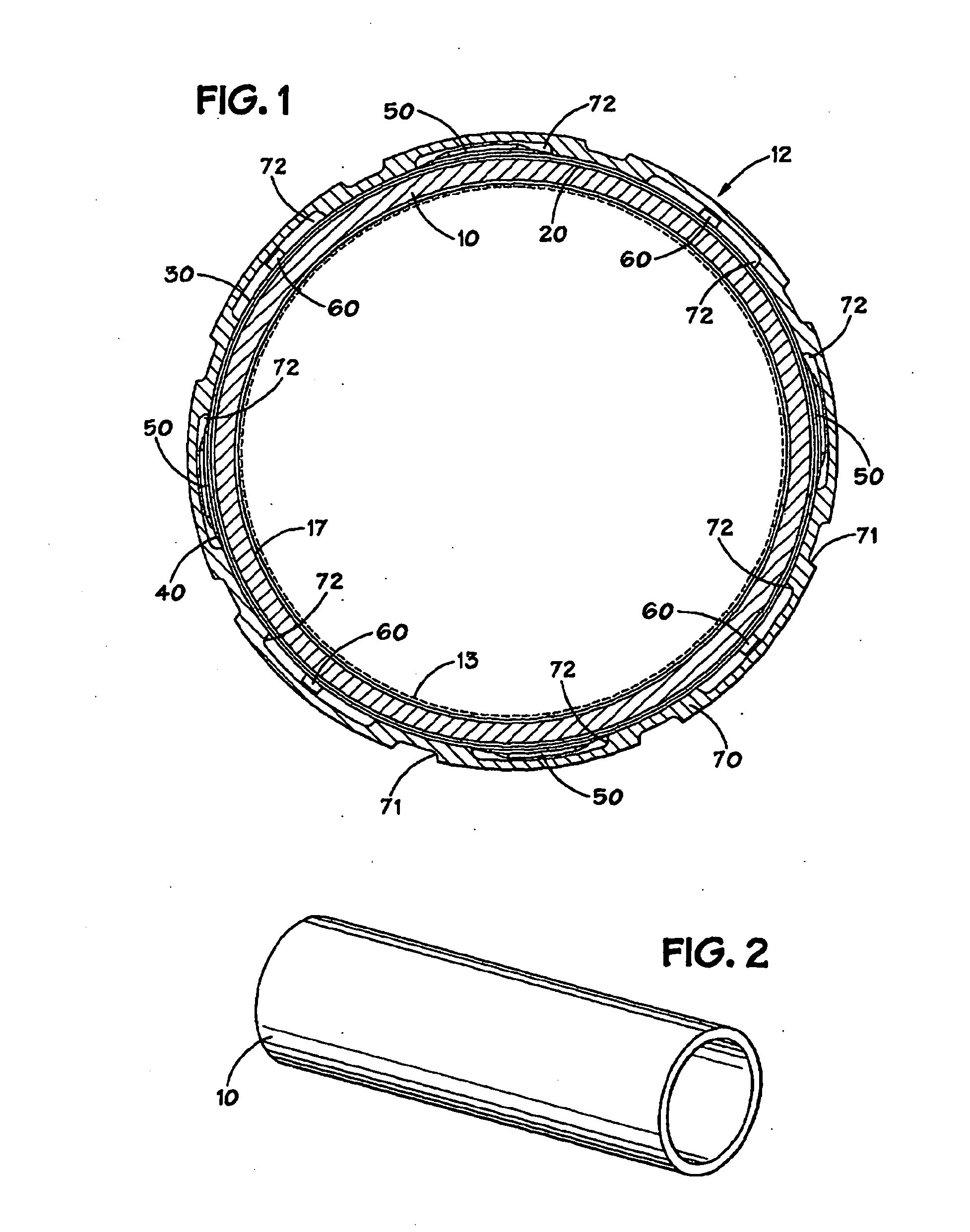
[0020]In one particular aspect a first layer of a pipe according to the present invention is a first polymeric layer which is an extruded cylindrical
thermoplastic or modified thermosetting resin material, such as
polyolefin, polyamides, polyvinyl chlorides and alloys thereof, HDPE and polymeric materials that have sufficient resistance to
chemical attack and strength to be used in applications involving the transport of hydrocarbons and water. Such materials are readily available worldwide and have had extensive usage in the transportation of
natural gas, hydrocarbons and water. An extruded cylinder is produced in long, yet transportable, lengths for ease of inspection and transport to the fabrication site. These discrete length cylinders of polymeric material are welded together, e.g. butt fusion welded, to form a continuous-length inner pressure barrier for the pipe. The weld is accomplished using existing technology in conjunction with, preferably, rapid cooling techniques, to increase the process speed. Both the external and internal weld beads are, optionally, removed during the process and each weld is subjected to a 100% volumetric non-destructive integrity test.
[0022]In certain aspects the material used is one of several advanced reinforcement fiber materials commonly referred to as “ballistic materials” or “extended chain
polyethylene ballistic material”. This material is light weight, exhibits high
specific strength, high specific stiffness and low elongation or stretch.
[0025]In addition to the
monitoring system, additional fiber optic cables can be provided for use in a communications and
control system. These fiber optic cables can be included within the tapes mentioned or within separate tap The
monitoring system package and reinforcement is, optionally, protected by a polymeric cover or jacket. This placement can result in an annular space between the pipe reinforcement and the inside of the cover sheet due to the presence therebetween of the fiber optic sensors. Spacers are, optionally, placed between the sensor tapes as necessary to support the cover (e.g., separate spacers made of plastic, wood, extruded
thermoplastic or thermosetting material or spacers that are integral to a cover). Additionally, in certain aspects, these spacers are, optionally, shaped to permit the accumulation of permeated fluids from the flowing fluid to be vacuumed at an external vent port so there is no accumulation of pressure that might result in damage to the pipe liner. Monitoring the amount of fluid removed and / or pressure relieved provides an additional indication of the integrity of the pipe liner.

