
Apparatus and Method for Multi-Component Wellbore Electric Field Measurements Using Capacitive Sensors

a capacitive sensor and multi-component technology, applied in the direction of instruments, survey, wellbore/well accessories, etc., can solve the problems of inability to measure the electric field in multi-components, prevent the development of reliable electric field measurement devices in wellbores, and the development of reliable electric field sensors. achieve the effect of low power

Active Publication Date: 2012-11-22
SAUDI ARABIAN OIL CO
View PDF35 Cites 37 Cited by
  • Summary
  • Abstract
  • Description
  • Claims
  • Application Information

AI Technical Summary

Benefits of technology

[0015]Capacitive electric field sensors operate in free-space, without electrical contact to any object. This technology allows components of the electric-field to, be measured in three dimensions within the bore hole, either static or moving slowly. The technology has no moving parts and is low power. In addition, because it does not couple to the formation via a chemical reaction the measurement is much more reliable and does not depend on the local environmental conditions, such as pressure, temperature and chemistry. The capacitive electrode technology can be also used in extremely dry ground typical of desert environments. This has the advantage of not requiring electrolyte, such as what is used in a conventional porous pot electrode, to operate, and so can be deployed permanently at the reservoir level without need of maintenance.

Problems solved by technology

Technical limitations have prevented so far the development of reliable electric-field sensors able to be deployed permanently in the reservoir in vertical, deviated and horizontal wells.
Some of these limitations are related to the inability to measure the electric field in multi-components under borehole conditions.
Device dimensions and the need of providing an effective low contact resistance with the rock formations have prevented the development of reliable borehole electric field measurement devices.

Method used


Image

  • Apparatus and Method for Multi-Component Wellbore Electric Field Measurements Using Capacitive Sensors
  • Apparatus and Method for Multi-Component Wellbore Electric Field Measurements Using Capacitive Sensors
  • Apparatus and Method for Multi-Component Wellbore Electric Field Measurements Using Capacitive Sensors

Examples


Embodiment Construction

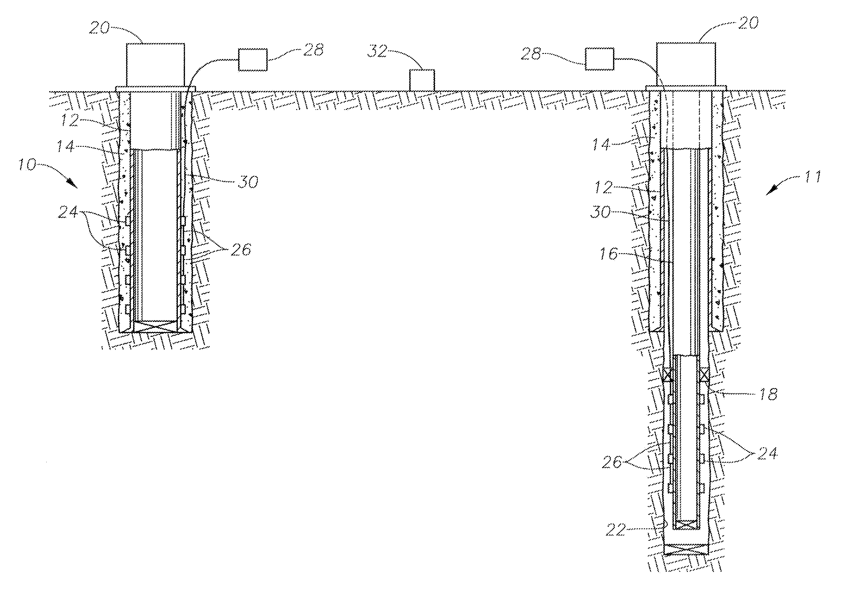
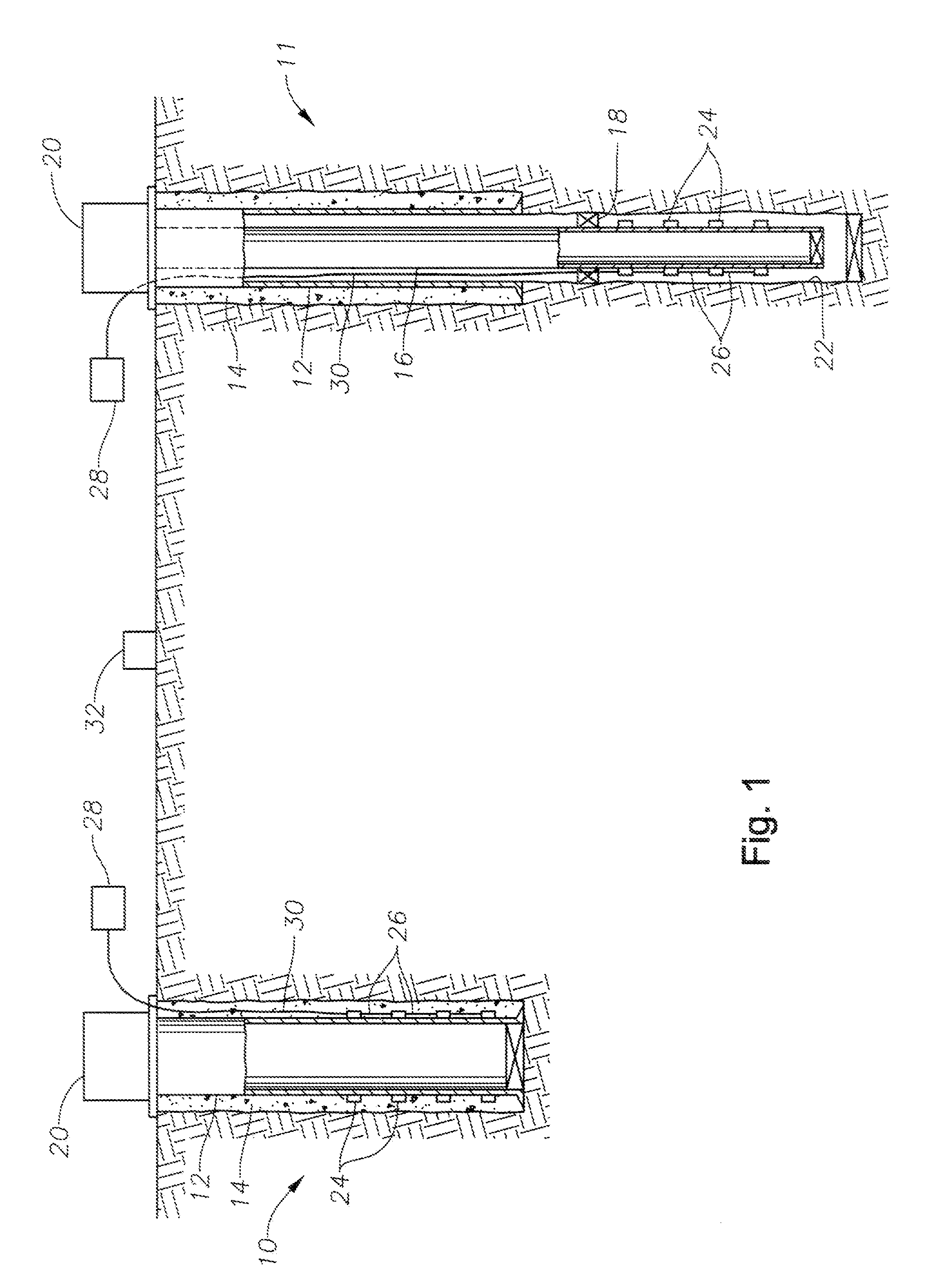
[0031]As seen in FIG. 1, the system of the current invention may be employed in multiple subterranean wells. One well 10 may be cased with casing 12. Cement 14 surrounds casing 12 and both the casing and cement extend to the bottom of the well. Another well 11 may also be cased with casing 12, which is surrounded by cement 14, but does not extend to the bottom of the well. Well 11 may additionally have production tubing 16 that extends downward into a open portion 22 of the well, below the bottom of the casing 12 and cement 14. Packer 18 seals in the tubing 16 within well 11. Each of wells 10, 11 will have a well head 20. The wells may have vertical, deviated or horizontal boreholes.

[0032]In the embodiment of FIG. 1, electromagnetic sensor units 24 are positioned within both well 10 and well 11. In alternative embodiments, the sensor units 24 may be in one well or more than two wells. The sensor units 24 are connected to each other by an electrical umbilical segment 26 and the upper...


PUM


Abstract

A method and apparatus is provided for collecting reservoir data. The method includes providing one or more electromagnetic sources for generating an electromagnetic field in a reservoir and providing one or more electromagnetic sensors equipped with capacitive electrodes. The electromagnetic source is located separately from the electromagnetic sensor. The electromagnetic sensor may either be located within a well or at the surface, is capable of measuring the electromagnetic field in three dimensions, and may be isolated from the well fluids. The data collected by the electromagnetic sensors can be used to create a model of the oil reservoir, including the water saturation.

Description

BACKGROUND OF THE INVENTION[0001]1. Field of the Invention[0002]The present invention relates to an apparatus and method for evaluating oil and gas reservoir characteristics. More specifically, the invention relates to tri-axial field sensors for low frequency electromagnetic fields.[0003]2. Description of the Related Art[0004]Various segments of the energy industry have a need for remote sensing technology to complete such tasks as evaluating oil reserves depletion, optimizing oil recovery, and monitoring underground water, gas and CO2 injection and storage.[0005]It is well known that the ability to measure in a reliable way the electric field components in a borehole environment is of great value to implement electromagnetic-based characterization and monitoring techniques for reservoir fluids. It is also well known that permanent installation of such sensors would enable the optimization of oil field production. Current electric field sensors are very sensitive to environmental c...

Claims


Application Information

Patent Timeline
Patent Type & Authority Applications(United States)
IPC IPC(8): G01V3/18
CPCG01V3/26E21B47/00G01V3/28G01V3/18G01V3/10Y02A90/30
Inventor COLOMBO, DANIELEKEHO, TIMOTHY H.JERVIS, MICHAEL ANTHONYBOULDIN, BRETT W.
Owner SAUDI ARABIAN OIL CO
Learn More