
Method and system for multi-point signal generation with phase synchronized local carriers

a local carrier and multi-point signal technology, applied in the direction of generating/distributing signals, digital transmission, pulse automatic control, etc., can solve the problems of insufficient electrically small miniaturized systems such as fully integrated circuits, the design of distribution networks providing accurate synchronization may become extremely difficult, and the practical limitations are well documented

Active Publication Date: 2012-11-22
NEC ADVANCED NETWORKS INC
View PDF1 Cites 35 Cited by
  • Summary
  • Abstract
  • Description
  • Claims
  • Application Information

AI Technical Summary

Benefits of technology

This approach reduces the need for excessive transmission line lengths, minimizes signal loss, and maintains precise phase synchronization across the system, even with modulated signals, thereby overcoming the limitations of existing methods.

Problems solved by technology

However, in most modern applications, the carrier frequencies are so high (e.g., on the order of GHz) that even miniaturized systems, such as fully integrated circuits, are not electrically small.
In such cases, the design of the distribution network providing accurate synchronization may become extremely challenging.
This approach is the de facto “work horse” of signal distribution / synchronization but suffers from well-documented practical limitations: stringent geometrical constraints, power hungry, susceptibility to noise, and susceptibility to timing errors known as skew.
Often, expensive additional techniques are employed to contain these shortcomings.
In the case of active distribution trees, such as those used in VLSI clocking, operation at frequencies above a few GHz is rather difficult to attain.
The main fundamental shortcomings of this technique are a) the large total length of the waveguides, possibly resulting in signal loss and dispersion, and b) the limited practical precision of the known time averaging circuits.
For these techniques, any pulse dispersion introduces timing errors, which increase as the pulses travel farther and farther away from the generators.
The first option increases the system cost and the second option reduces the number of useful applications.
Applying this approach with high speed optical pulses transmitted over optical wave-guides should provide significantly lower dispersion but such systems would require additional error-prone functionality related to optical-to-electrical conversion.
However, this theoretical simplicity is deceptive.
Such circuits cannot be used for accurate time averaging because the output harmonics introduce significant timing errors.
This is not a trivial design task for low cost applications such as VLSI clocking, where using integrated RF filters to clean up each multiplier output would not be economical.
The design of integrated multipliers with very low harmonic content is further complicated if the two multiplier inputs do not have the same magnitude.
Just as before, this limits the technique either in terms of cost through the requirement of implementing expensive low-loss transmission lines, or in limited application possibilities due to short total transmission line length.

Method used


Image

  • Method and system for multi-point signal generation with phase synchronized local carriers
  • Method and system for multi-point signal generation with phase synchronized local carriers
  • Method and system for multi-point signal generation with phase synchronized local carriers

Examples


Embodiment Construction

A Single-Frequency System Using Two-Level Trees

[0083]Embodiments of the present invention include the generation of at least two modulated signals at many points in space such that their carriers have the same frequency and are in precise phase relationship to each other.

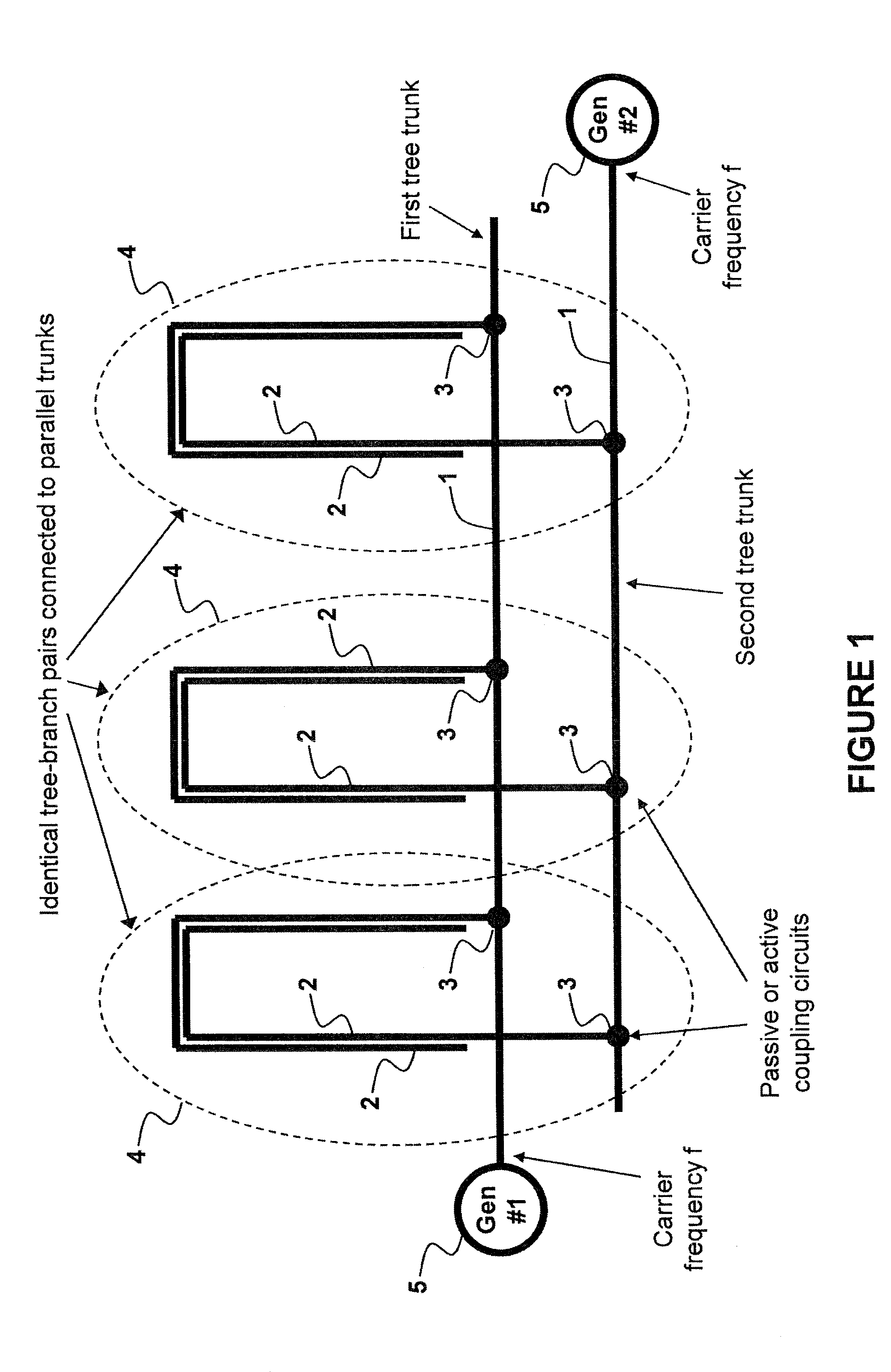
[0084]FIG. 1 depicts a schematic diagram of two independent tree networks, each consisting of a tree trunk 1 and tree branches 2. The tree trunk and the tree branches are properly terminated transmission lines (termination circuits are not shown in FIG. 1 for simplicity), such as electrical microstrip lines, optical wave-guides, or sound propagating guides. The difference between the trunk 1 and the branches 2 is not in substance but rather in name, based on the relative position of the transmission lines (TL) with respect to the tree network input port. The trunk 1 is defined as the transmission line connected directly to the input port. The branches 2 are coupled to the trunk 1 through passive or active circuits 3...


PUM


Abstract

A method and system of applying modulated carrier signals to tree networks and processing signals tapped from the tree networks to generate output signals with phase-synchronized carriers are disclosed.

Description

CROSS REFERENCE TO RELATED APPLICATIONS[0001]This application is a continuation of U.S. patent application Ser. No. 12 / 176,897, filed Jul. 21, 2008, which claims priority to U.S. Provisional Application No. 60 / 961,367, filed Jul. 20, 2007, each of which is incorporated herein by reference in its entirety.BACKGROUND OF THE INVENTION[0002]1. Field of the Invention[0003]Embodiments of the present invention generally relate to analog and digital signal distribution / synchronization methods and systems and in particular to the distribution of a modulated signal in a coherent system to achieve carrier phase / frequency synchronization at the distribution points.[0004]2. Description of the Related Art[0005]Many analog and digital systems and subsystems used in communications, computing, data processing, military, and other applications (collectively hereinafter referred to as “coherent systems”) are designed to operate synchronously. Typical coherent systems comprise subsystems capable of gen...

Claims


Application Information

Patent Timeline
Patent Type & Authority Applications(United States)
IPC IPC(8): H04L7/00
CPCG06F1/12H04L7/02H04B2215/067H04B15/02
Inventor BANU, MIHAIPRODANOV, VLADIMIR
Owner NEC ADVANCED NETWORKS INC
Learn More