Underwater hydrocarbon transport and temperature control device

a technology of temperature control device and hydrocarbon, which is applied in the direction of pipe heating/cooling, insulation, borehole/well accessories, etc., can solve the problems of additional force on the pipeline, inability to economically viable approaches, damage or destruction of electronic components, etc., and achieve simple and robust devices. high thermal power

Active Publication Date: 2012-11-29
ITP
View PDF0 Cites 37 Cited by
  • Summary
  • Abstract
  • Description
  • Claims
  • Application Information

AI Technical Summary

Benefits of technology

[0035]Another advantage of the present invention lies in that a high thermal power of around 1 MW to 50 MW can be dissipated by a simple and robust device.
[0036]Another advantage of the present invention lies in the fact that, during production stoppages, the hydrocarbon transport device positioned at the wellhead can be kept at temperatures enabling production to be started up again.
[0037]Another advantage of the present invention lies in that the transport device position at the well outlet constitutes a heat dissipating system that can withstand particularly well any fouling of the exchange surfaces since it uses a large area of piping to perform the heat exchanges. The transport device made in the form of a single assembly, called “bundle”, intended to be towed out to sea for its installation, may, for example, be several kilometers in length, typically 8 km, but even up to several tens of kilometers.

Problems solved by technology

One technical problem is thus to provide installations adapted to these temperatures, both to support the thermal expansion by resisting to the stresses or by authorizing and controlling them, and to select materials adapted to these temperatures.
These approaches are not economically viable in the case of pipelines of several kilometers or several tens of kilometers in length and for which free expansion can reach several meters per kilometer.
Restraining the thermal expansion thus results in additional force exerted on the pipeline.
Even downstream of the well outlet, after part of the heat has dissipated, high temperatures can remain and cause technical problems.
Electronic components may also be damaged or destroyed at temperatures above their maximum operating temperature.
Moreover, such a solution is not satisfactory for production stoppages involving a risk of forming plugs of hydrocarbons in the non-insulated part.
Indeed, the temperature of the effluent cannot be allowed decrease to the temperature of the sea environment, typically 4° C., since this could lead to the formation of gas hydrates and other solids which could block the hydrocarbon pipeline.
Another issue is the variation of pressure and temperature at the well head as the oil reservoir is being exploited.

Method used


Image

  • Underwater hydrocarbon transport and temperature control device
  • Underwater hydrocarbon transport and temperature control device
  • Underwater hydrocarbon transport and temperature control device

Examples


Embodiment Construction

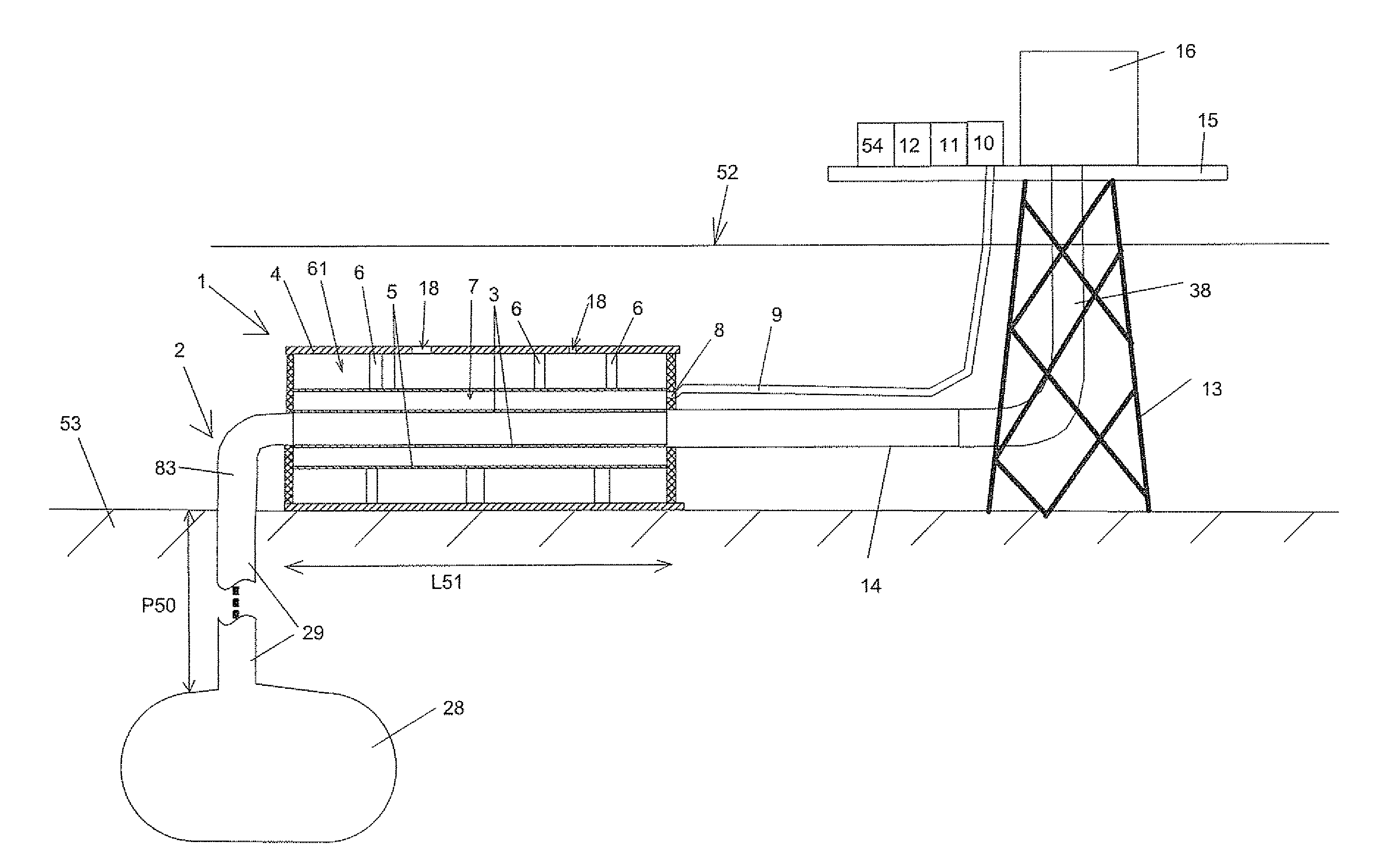
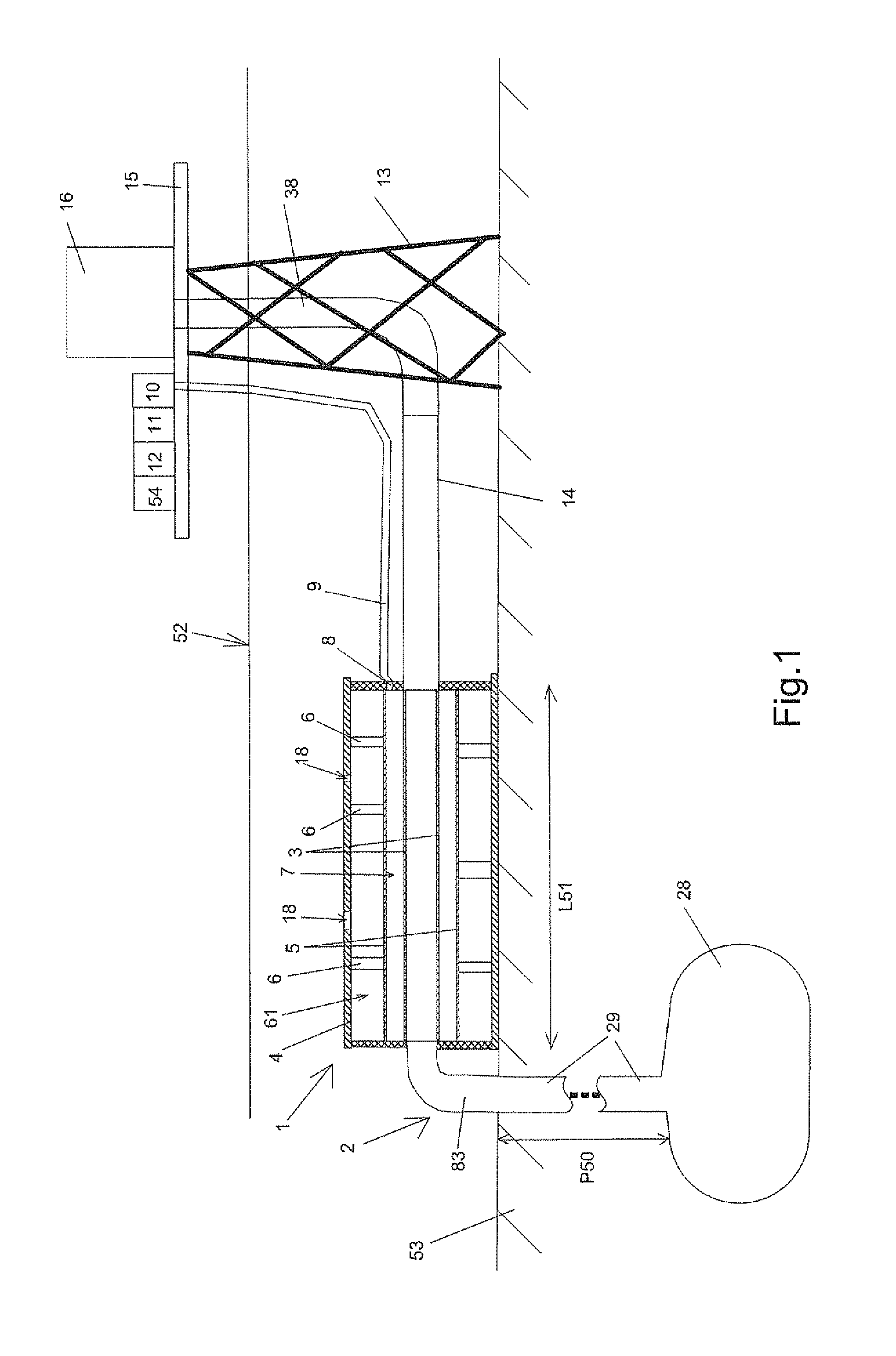
[0049]FIG. 1 shows an immersed hydrocarbon transport device 1 arranged at the head of an extraction well 2. A deep pool of hydrocarbons is schematized by a pocket 28 to which access is made by a drill 29. The drill 29 is linked under water to the well head 2. The pool of hydrocarbons lies at a depth P50 of, for example, between 4000 and 8000 meters, or more. A well outlet pipe 83 links the drill 29 to the transport device 1. This pipe 83 is a classical pipe that does not, in itself, cause any significant change in temperature.

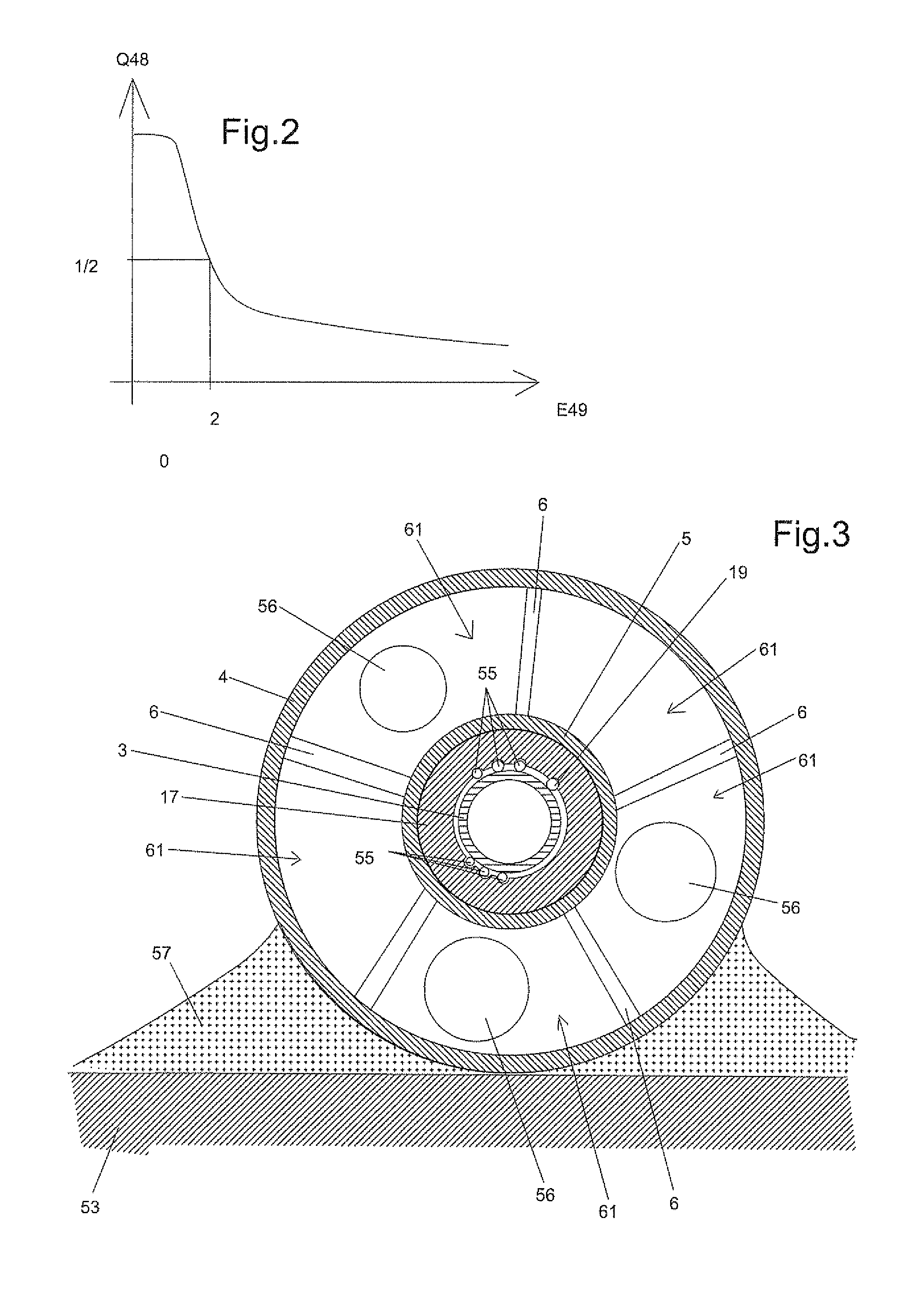
[0050]The transport device 1 according to the invention comprises a first pipe 3 into which the fluid arrives from the extraction well 2. A second pipe 5 is arranged around and at a distance from the first pipe 3. The first and second pipes 3 and 5 are held in relation to one another by assembly elements and form a pipe-in-pipe. An annular space 7 is arranged between these two pipes 3 and 5.

[0051]The pipe-in-pipe is arranged in an external protective casing 4. ...


PUM


Abstract

The invention relates to a hydrocarbon transport device intended to be immersed and arranged at an extraction wellhead, comprising a first pipe through which a first fluid leaving the extraction well flows, the first pipe being arranged in an external protective casing, a piloting system to pilot the temperature in the first pipe controlling an activation element of a regulating system for regulating a heat exchange between the first pipe and the liquid medium filling the immersed external casing, the regulating system comprising at least a second pipe arranged around the first pipe and delimiting an annular space enclosing at least one regulating fluid, this regulating fluid being injected into or expelled from the annular space by the activation element of the regulating system.

Description

BACKGROUND OF THE INVENTION[0001]1. Field of the Invention[0002]The technical scope of the present invention is that of hydrocarbon transport pipes able to regulate the temperature of the hydrocarbons.[0003]2. Description of Related Art[0004]To prepare for the depletion of subsea oil fields at low and medium temperature, which is to say at a temperature of less than 120° C., oil producers are obliged to exploit the deep geological layers of the subsea oil reserves, for example at depths of around 4000 or 6000 meters, or even deeper. Because of a mean geothermal gradient of 30° C. / km, the hydrocarbons leaving the oil wells can reach temperatures of over 150° C. The temperatures observed can be, for example 210° C. or even 240° C. at the wellhead.[0005]One technical problem is thus to provide installations adapted to these temperatures, both to support the thermal expansion by resisting to the stresses or by authorizing and controlling them, and to select materials adapted to these te...

Claims


Application Information

Patent Timeline
Patent Type & Authority Applications(United States)
IPC IPC(8): F16L53/00F16L53/32
CPCF16L53/002F16L53/32Y10T137/6579Y10T137/7036F16L53/00E21B36/003E21B36/005
Inventor GEERTSEN, CHRISTIAN
Owner ITP
Why Eureka
Try Eureka