Compensation Methods for Digital Source-Measure-Units (SMUs)

Active Publication Date: 2012-12-06
NATIONAL INSTRUMENTS
View PDF2 Cites 22 Cited by
  • Summary
  • Abstract
  • Description
  • Claims
  • Application Information

AI Technical Summary

Benefits of technology

[0016]The readback values (for the measured current and/or voltage) may be obtained by averaging the current and/or voltage values received from the ADCs. The averaging may be weighted to provide noise rejection advantages. Placing the control loop in the digital domain may result in added flexibility of the SMU, and a decrease in the accuracy requirements on the DAC. The digital control loop may also offer the possibility of novel approaches for solving potential range-switching issues that may arise within the SMUs.
[0017]In one set of embodiments, an SMU may comprise output terminals configured to couple the SMU to a DUT, and further configured to convey an analog output signal to the DUT to effect an output current flowing into the DUT and an output voltage in the DUT. The SMU may include a first converter configured to generate a first digital value representative of the output current, a second converter configured to generate a second digital value representative of the output voltage, and a digital loop controller configured to receive the first digital value and the second digital value, and generate a digital control signal based on the first digital value and the second digital value to regulate a specified function of the output current and the output voltage to remain at a value corresponding to a setpoint. The specified function may be the output current, the output voltage, power, or resistance, to name a few. The first digital value, being representative of the output current, may correspond to a current measurement, and the second digital value being representative of the output voltage may correspond to a voltage measurement. The first digital value and second digital value may therefore effectively be used in measuring and/or controlling any function, which may be defined and/or processed in the digital loop controller. For example, multiplying the first digital value and the second digital value may provide a measurement of power. Accordingly, the digital control value may be generated by the digital loop controller to effect desired changes in the output current and/or the output voltage depending on what the selected function is. For example, if the selected function is power, then both the output current and output voltage ma

Problems solved by technology

Placing the control loop in the digital domain may result in added flexib

Method used


Image

  • Compensation Methods for Digital Source-Measure-Units (SMUs)
  • Compensation Methods for Digital Source-Measure-Units (SMUs)
  • Compensation Methods for Digital Source-Measure-Units (SMUs)

Examples


Embodiment Construction

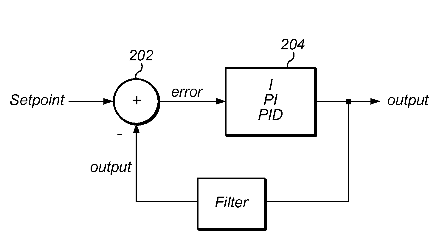
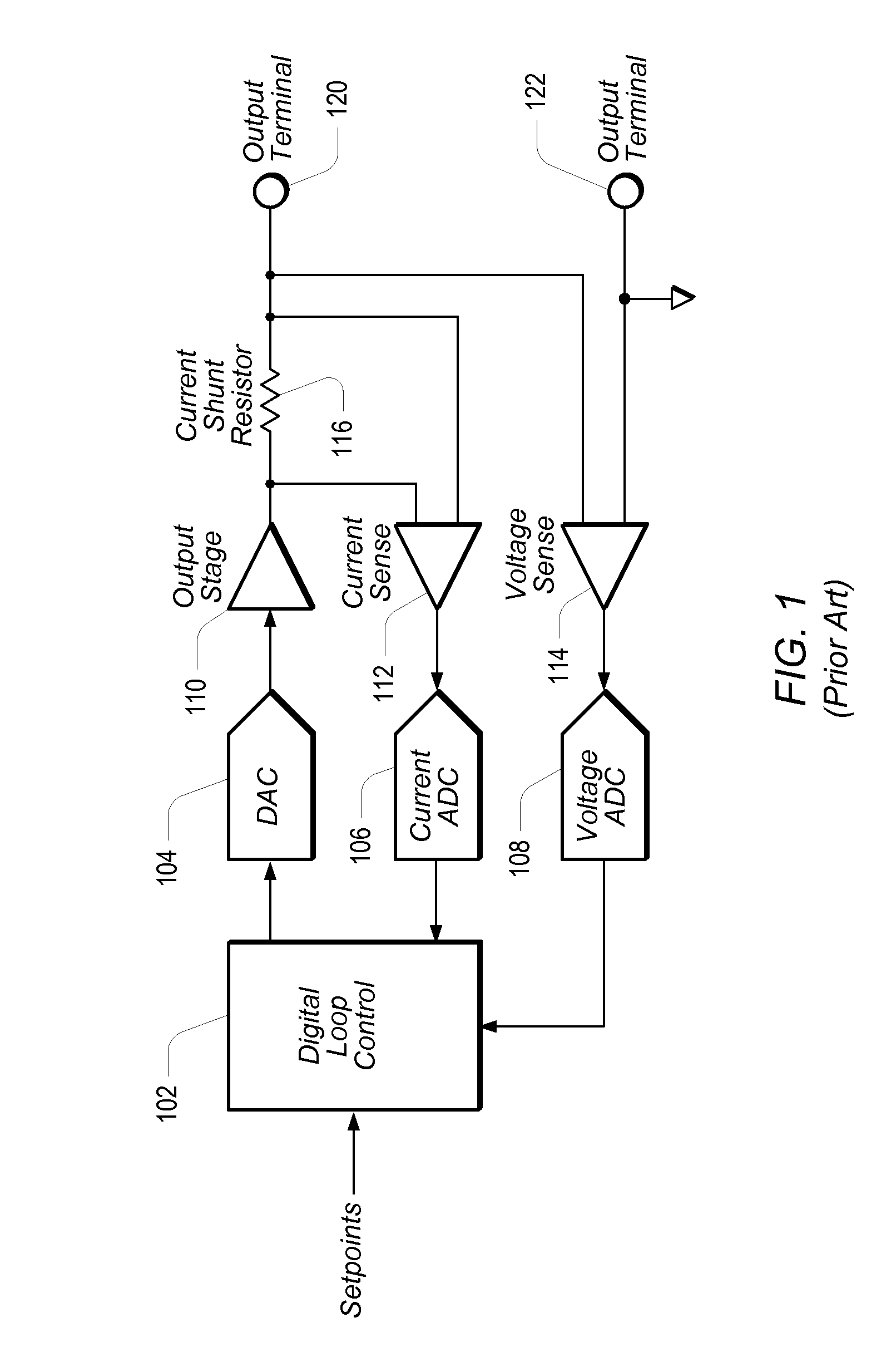
[0036]FIG. 1 shows the basic architecture of one embodiment of a prior art SMU (source-measure unit) in which the entire control loop has been configured in the digital domain. A DUT (device under test), not shown, may be coupled between output terminals 120 and 122. Setpoints and compliance limits may be provided (programmed) to Digital Loop Controller (DLC) 102, which may provide a control output through DAC (digital-to-analog converter) 104 to Output Stage 110. Feedback from Output Stage 110 may be provided to Current ADC (analog-to-digital converter) 106 and Voltage ADC 108 via respective Current Sense element 112 and Voltage Sense element 114. The current feedback may be taken from the current flowing through current shunt resistor 116, and the feedback voltage may be taken from across output terminals 120 and 122. Current ADC 106 and Voltage ADC 108 may then provide the readback current and voltage values into DLC 102.

[0037]DLC 102 may be configured to check the measured curre...


PUM


Abstract

A source-measure unit (SMU) may be implemented with respective digital control loops for output voltage and output current. The output voltage and output current may be measured with dedicated ADCs (analog-to-digital converters). The readings obtained by the ADCs may be compared to a setpoint, which may be set in a digital loop controller. The digital loop controller may be used to produce an output to drive a DAC (digital-to-analog converter) until the output voltage and/or output current and/or a function thereof reach the respective desired levels. The digital loop controller may implement respective integrating functions for the respective digital control loops, and may also implement a compensation function featuring pole-zero pairs to stabilize the respective current/voltage outputs. Coefficients of the compensation function may be calculated based on user programmable parameters corresponding to the gain bandwidth product, compensation frequency, and ratio of the added pole-zero frequencies.

Description

INCORPORATION BY REFERENCE[0001]U.S. Pat. No. 7,903,008 B2 is hereby incorporated by reference as though fully and completely set forth herein.BACKGROUND OF THE INVENTION[0002]1. Field of the Invention[0003]This invention relates generally to measurement and data acquisition systems and, more particularly, to the design of digital source-measure units.[0004]2. Description of the Related Art[0005]Scientists and engineers often use measurement systems to perform a variety of functions, including measurement of a physical phenomena a unit under test (UUT) or device under test (DUT), test and analysis of physical phenomena, process monitoring and control, control of mechanical or electrical machinery, data logging, laboratory research, and analytical chemistry, to name a few examples.[0006]A typical measurement system comprises a computer system, which commonly features a measurement device, or measurement hardware. The measurement device may be a computer-based instrument, a data acqui...

Claims


Application Information

Patent Timeline
IPC IPC(8): G01R31/00
CPCG01R31/2841
Inventor REGIER, CHRISTOPHER G.ORTEGA-POHLENZ, L. ROLANDO
Owner NATIONAL INSTRUMENTS
Why Eureka
Try Eureka