
Patient-specific manufacturing of porous metal prostheses

a technology of porous metal prostheses and patient-specific manufacturing, which is applied in the direction of prosthesis, additive manufacturing process, impression cap, etc., can solve the problems of reducing the degree of arbitraryity, the inability to precisely shape the substrate, and the inability to meet the needs of patients, so as to avoid substantially changing the porosity of the structure, the amount of breakage, deformation, and/or crushing may be minimized, and the effect of reducing the amount of efficiency

Active Publication Date: 2012-12-06
ZIMMER INC
View PDF1 Cites 180 Cited by
  • Summary
  • Abstract
  • Description
  • Claims
  • Application Information

AI Technical Summary

Benefits of technology

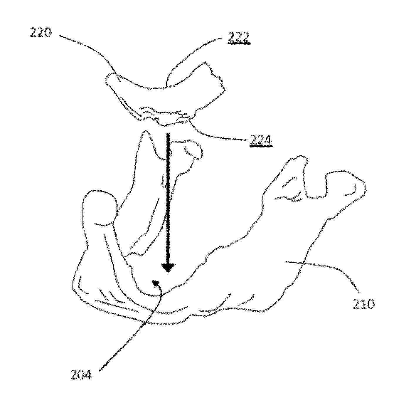
[0011]The prosthesis model may be a digital model that is designed using a suitable computer planning system having, for example, computer-aided design (CAD) software. The computer planning system may allow the designer to define or specify certain boundaries of the prosthesis model. For example, the computer planning system may allow the designer to define or specify the shape of an exposed surface or an articulating surface of the prosthesis model. The computer planning system may automatically define other boundaries of the prosthesis model. For example, the computer planning system may automatically define the shape of a bone-contacting surface of the prosthesis model as substantially a negative of the bone model so that the prosthesis model conforms to the bone model and is perfectly contoured to fit against the bone model. In this manner, once manufactured, a patient-specific, bone-contacting surface of the orthopaedic prosthesis may also be shaped as substantially a negative of the patient's bone such that the patient-specific surface of the orthopaedic prosthesis conforms to the patient's bone and is perfectly contoured to fit against the patient's bone, even a substantially uncut or unreamed surface of the patient's bone that is highly irregular, arbitrary, non-parametric, or biologically complex. The computer planning system may also allow the designer to add sockets, channels, recesses, or other features to the prosthesis model, thereby allowing the orthopaedic prosthesis to receive suitable fasteners (e.g., bone screws) or tools, for example. In summary, the computer planning system allows the designer to accommodate the needs of the particular patient when designing the prosthesis model.
[0023]According to a preferred embodiment of the invention, the substrate is shaped in the mold by breakage, deformation, and / or crushing. The deformation that occurs during the shaping step is preferably minimized for efficiency and to avoid substantially changing the porosity of the structure. The amount of breakage, deformation, and / or crushing may be minimized by designing the mold to compress the structure in multiple, non-parallel directions.
[0024]After shaping, the substrate may be coated for example by a chemical vapor deposition (CVD) process. The coating step may strengthen the substrate for implantation, causing the substrate to become less readily shapeable than before the coating step.

Problems solved by technology

Because the prosthesis model is designed based on the traumatic injury or deterioration suffered by the particular patient and the surrounding anatomy of the particular patient, the desired shape of the prosthesis model may be highly irregular, arbitrary, and biologically complex, especially when the orthopaedic prosthesis represented by the prosthesis model will be used for a geometrically demanding application.
The coating step may strengthen the substrate for implantation, causing the substrate to become less readily shapeable than before the coating step.

Method used


Image

  • Patient-specific manufacturing of porous metal prostheses
  • Patient-specific manufacturing of porous metal prostheses
  • Patient-specific manufacturing of porous metal prostheses

Examples


Embodiment Construction

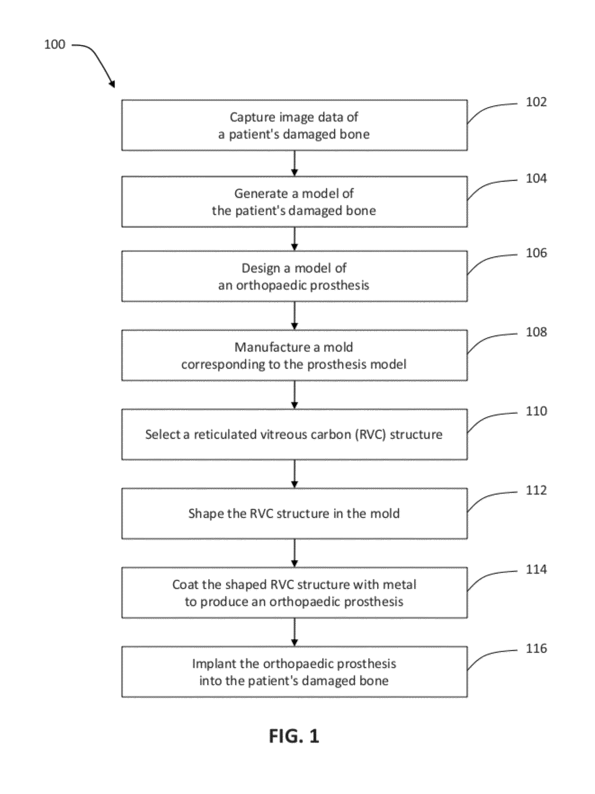
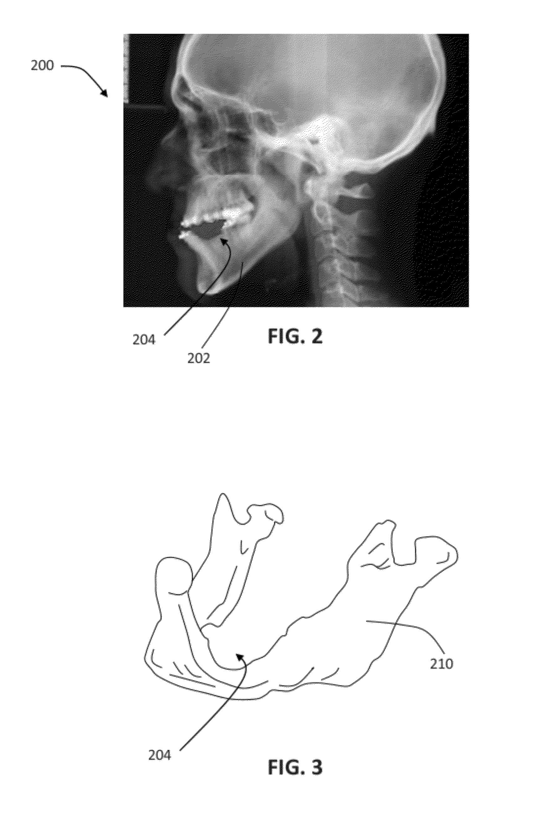
[0049]FIG. 1 provides an exemplary method 100 for designing and manufacturing a patient-specific porous metal prosthesis. Method 100 is exemplified with reference to FIGS. 2-9.

[0050]Beginning at step 102 of method 100 (FIG. 1), a surgeon or another party captures image data of a patient's damaged bone. The damaged bone may include all or part of the patient's maxilla, mandible, or another craniofacial bone. The damaged bone may also include all or part of the patient's femur, tibia, pelvis, humerus, or scapula, for example. The image data may be captured using a suitable imaging modality, such as X-ray, fluoroscopy, magnetic resonance imaging (MRI), computed tomography (CT), or ultrasound, for example. The image data may include two-dimensional views of the damaged bone, three-dimensional views of the damaged bone, or combinations thereof.

[0051]With reference to FIG. 2, for example, X-ray image 200 is captured showing the patient's damaged mandible 202 or lower jaw bone. In this exa...


PUM

PropertyMeasurementUnit
Sizeaaaaaaaaaa
Shapeaaaaaaaaaa
Biocompatibilityaaaaaaaaaa

Abstract

A patient-specific porous metal prosthesis and a method for manufacturing the same are provided. The orthopaedic prosthesis may be metallic to provide adequate strength and stability. Also, the orthopaedic prosthesis may be porous to promote bone ingrowth.

Description

CROSS REFERENCE TO RELATED APPLICATION[0001]This application claims priority from U.S. Provisional Patent Application Ser. No. 61 / 483,502, filed May 6, 2011, the disclosure of which is hereby expressly incorporated by reference herein in its entirety.FIELD OF THE DISCLOSURE[0002]The present disclosure relates to porous metal prostheses. More particularly, the present disclosure relates to patient-specific porous metal prostheses, and to a method for manufacturing the same.BACKGROUND OF THE DISCLOSURE[0003]Orthopaedic prostheses are commonly used to replace at least a portion of a patient's bone following traumatic injury or deterioration due to aging, illness, or disease, for example.[0004]When the orthopaedic prosthesis is implanted into a joint, the orthopaedic prosthesis may be configured to articulate with an adjacent orthopaedic component. For example, when the orthopaedic prosthesis is implanted into the patient's hip joint, the orthopaedic prosthesis may be socket-shaped to r...

Claims


Application Information

Patent Timeline
IPC IPC(8): A61F2/28B29C33/38
CPCA61F2/2803A61F2/30942A61F2002/3092A61F2002/30985A61F2002/30962A61F2002/30963A61F2002/3096A61F2310/00011B33Y10/00B33Y80/00B29C64/106B29C64/386F04C2270/041A61F2/30767A61F2/44A61F2002/3093A61F2002/30952A61F2002/30957B29C33/3842B29L2031/7532B33Y50/02C23C16/06C23C16/44
Inventor LI, JIACRON, SCOTT V.BASSETT, JEFFREYWILLIS, EDWARD M.
Owner ZIMMER INC
Learn More