Method for introducing feedback in a FET amplifier

a technology of introducing feedback and amplifier, which is applied in the direction of amplifier details, differential amplifiers, amplifiers with semiconductor devices/discharge tubes, etc., can solve the problems of relatively high input resistance and relatively low feedback resistance of high gain amplifiers used in the manner of operational amplifiers, and achieve the effects of reducing distortion, reducing input impedance, and reducing input impedan

Inactive Publication Date: 2012-12-13
SHAW COLIN
View PDF0 Cites 0 Cited by
  • Summary
  • Abstract
  • Description
  • Claims
  • Application Information

AI Technical Summary

Benefits of technology

[0002]The present invention depicts a method of configuring FET-based amplifiers in a current balancing circuit that allows for two direct gate inputs demonstrating arbitrary shunted input resistance and low series gate resistance. Used in a circuit with an output signal that is out of phase with the input, negative feed

Problems solved by technology

Both of these methods require numerous active devices in the form of current sources, current mirrors, gain stages, and the initial differential pair itself In addition to the employment

Method used


Image

  • Method for introducing feedback in a FET amplifier
  • Method for introducing feedback in a FET amplifier
  • Method for introducing feedback in a FET amplifier

Examples


Embodiment Construction

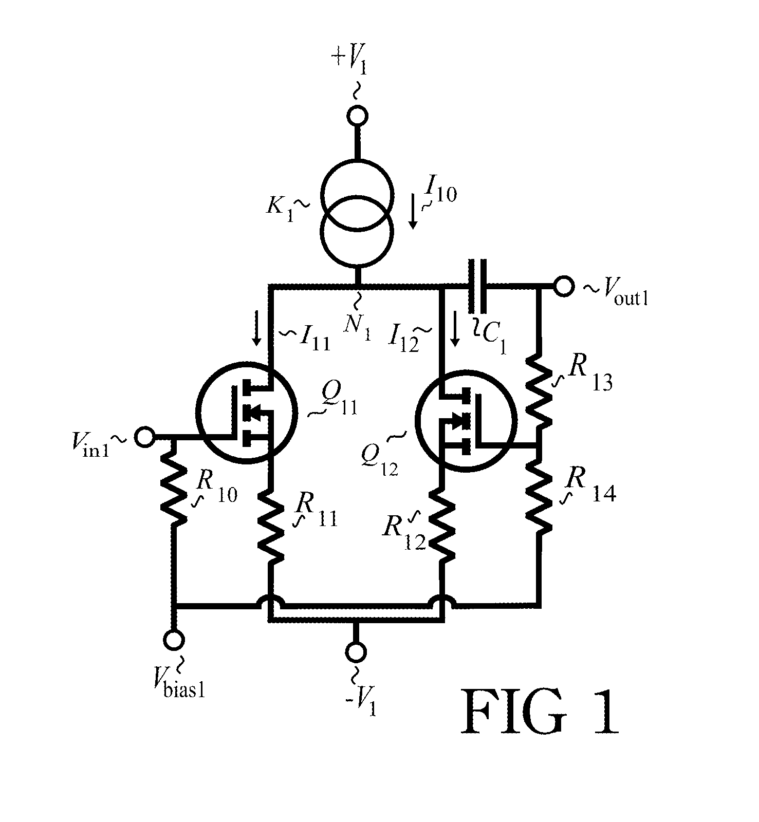
[0009]The topology of the amplifier depicted in FIG. 1 comprises a symmetrical arrangement of similar N-channel MOSFETs Q11 and Q12. A constant current source K1, fed by power supply +V1, produces a current I10 that is divided as evenly as is practical in the quiescent state between the two N-channel MOSFETs Q11 and Q12 at node N1, resulting in channel currents I11 and I12, respectively. It should be appreciated by those trained in the art that, while the invention is demonstrated by way of example using active, constant current sources, effects consistent with the spirit of the present invention can be achieved with constant voltage sources. Source resistors R11 and R12 have an induced voltage I11R11 and I12R12 that biases Q11 and Q12, respectively, resulting in, effectively, a two transistor degenerated amplifier with resistors R11 and R12 terminating in power supply −V1. R11 and R12 are typically similar in value, though gate-source offset variations in Q11 and Q12 can be accom...


PUM


Abstract

A method of configuring a FET amplifier with two inputs demonstrating similar-phased response to similar-phased inputs. One input can be used as a feedback path in suitable amplifier circuits, improving frequency performance by decreasing feedback resistance. The second input provides the means for a high impedance connection to a drive signal. The present invention is particularly applicable to applications involving constant voltage sources and constant current active sources with or without cascoding, in both single-ended and differential configurations.

Description

BACKGROUND OF THE INVENTION[0001]There are several methods currently used to develop feedback in an amplifier. One technique is to use a differential pair to accommodate negative feedback by using one side of the differential pair for a single-ended input and the other as a feedback path. This can be accomplished directly, as illustrated by U.S. Pat Nos. #4,107,619, #4,188,588 and #5,260,672, or more abstractly in high gain amplifiers vis-a-vis well known operational amplifier feedback methods. Both of these methods require numerous active devices in the form of current sources, current mirrors, gain stages, and the initial differential pair itself In addition to the employment of numerous active devices, high gain amplifiers used in the manner of operational amplifiers suffer the problem of relatively low input resistance and relatively high feedback resistance.BRIEF SUMMARY OF THE INVENTION[0002]The present invention depicts a method of configuring FET-based amplifiers in a curren...

Claims


Application Information

Patent Timeline
IPC IPC(8): H03F3/45H03F1/22
CPCH03F1/223H03F1/342H03F3/45376H03F2203/45564H03F2203/45512H03F2203/45526H03F2203/45528H03F2203/45481
Inventor SHAW, COLIN
Owner SHAW COLIN
Why Eureka
Try Eureka