Invasive cardiac valve

a cardiac valve and stent technology, applied in the field of invasive cardiac valves, can solve the problems of valve stenosis or regurgitation, endanger patient's life, bleeding or thromboembolism, etc., and achieve the effect of reducing the force effect, preventing the displacement of cardiac valves, and effectively preventing the risk of surrounding leakag

Active Publication Date: 2012-12-13
SHANGHAI MICROPORT CARDIOFLOW MEDTECH CO LTD
View PDF2 Cites 55 Cited by
  • Summary
  • Abstract
  • Description
  • Claims
  • Application Information

AI Technical Summary

Benefits of technology

[0036]Different designs of the width of the stent rod and different stent unit (grid) structures make the cardiac valve provide a uniform radial support force after being implanted to prevent the cardiac valve displacement caused by the impact of the blood flow.
[0037]Different designs of the width of the stent rod and different stent unit structures make the circumferential shape of the stent be deformable properly to be effectively attached to the portion of the aortic annulus.
[0038]The distinctive valve suture design can effectively prevent the risk of leakage of the surrounding of the vessel after the implantation of the cardiac valve.
[0039]The distinctive suture design of the joint position and joint point of the valve leaflet can effectively reduce the force effect produced on the stent during the running process of the valve and increase the durability of the stent.
[0040]The distinctive design of the shape of the biological valve leaflet increases the durability during the running process of the valve.
[0041]The size of the carrier matched with the present invention is comparatively small (18 F), which can effectively reduce the stimulation and damage to the vessel; and the head end of the carrier can be bent through a handle, which accords with the biological makeup of the aortic arch to avoid the damage to the aortic arch portion.

Problems solved by technology

The anticoagulant has many adverse side effects, e.g., it is very likely to cause bleeding or thromboembolism.
However, after the biological valve is implanted in the patient's body, the leaflet will undergo an early-mid-phase calcification, thereby resulting in valve stenosis or regurgitation.
Such a balloon-expanded biological valve has the following disadvantages and problems: during the process of the compression of the stent and the expansion of the balloon, the tissue structure of the leaflet of the biological valve will suffer great damage, which severely affects the service life of the cardiac valve after the implantation; the stent of the cardiac valve is decided by the diameter of the balloon, if the selected size is too small, the valve has the risk of looseness or displacement, whereby a secondary balloon expansion is the only choice, and if the selected size is too large, there is a risk of tearing the aortic annulus, which results in the occurrence of other complications; with respect to such a cardiac valve, the balloon cannot be reset once it is expanded, and it will endanger the patient's life on the spot under the circumstance where the valve is placed in an improper position; and once the cardiac valve is implanted, if a problem arises, the valve cannot be retrieved and can be only replaced by means of a surgical operation.
Such a self-expanded biological valve has the following disadvantages and problems: the stent is too long, and the design of the opening is unideal, which is likely to affect the hemodynamics of the left and right coronary ostia and results in disorder of the heart function; the cardiac valve which is released improperly cannot be reset, which will endanger the patient's life; and once the cardiac valve is implanted, if a problem arises, the valve cannot be retrieved and can be only replaced by means of a surgical operation.
Such a cardiac valve has the following disadvantages and problems: the stent is woven by threads, during the processes of compression and expansion, the grid is likely to be deformed, and the radial support force is unstable; there are a number of barbs at the outer side of the stent, although serving the purpose of preventing the displacement, they have a comparatively large damage to the vessel wall, meanwhile after the endothelialization, the retrieval of the stent is likely to tear the vessel, and the expected retrieval object is difficult to achieve; the design of the stent considers the positions of the left and right coronary ostia, but only two to three openings are left, the effect on the left and right coronary blood flows cannot be eliminated, and the positioning can hardly be performed when the cardiac valve is released.
It has been difficult to make much progress in the exploration of all the current products that have been clinically applied in the structure field.
The current biological cardiac valve cannot be reset once it is opened, and it will endanger the patient's life on the spot under the circumstance where it is placed in an improper position.

Method used


Image

  • Invasive cardiac valve
  • Invasive cardiac valve
  • Invasive cardiac valve

Examples


embodiment 1

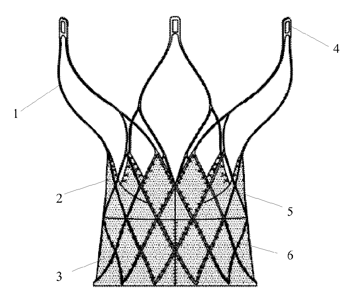
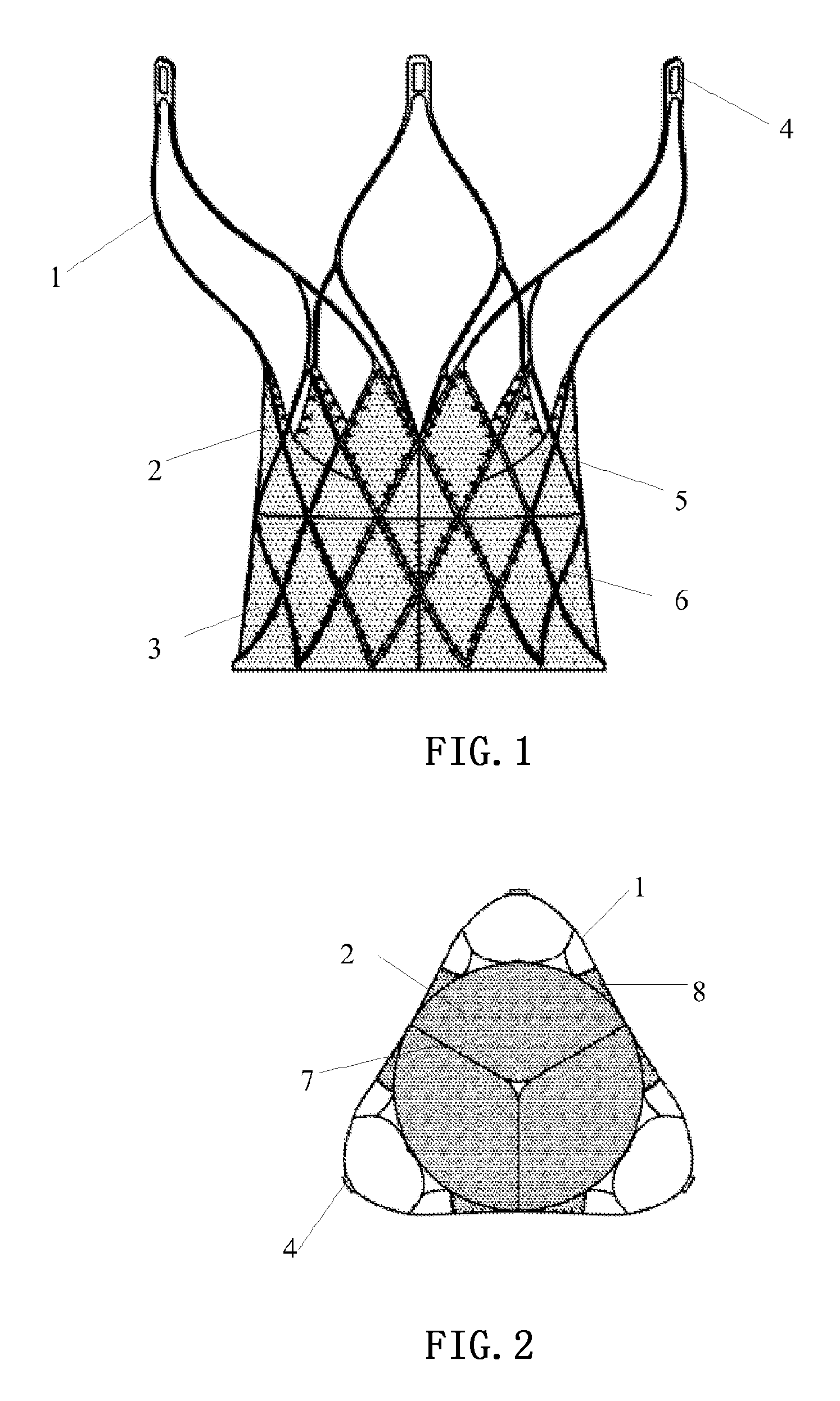
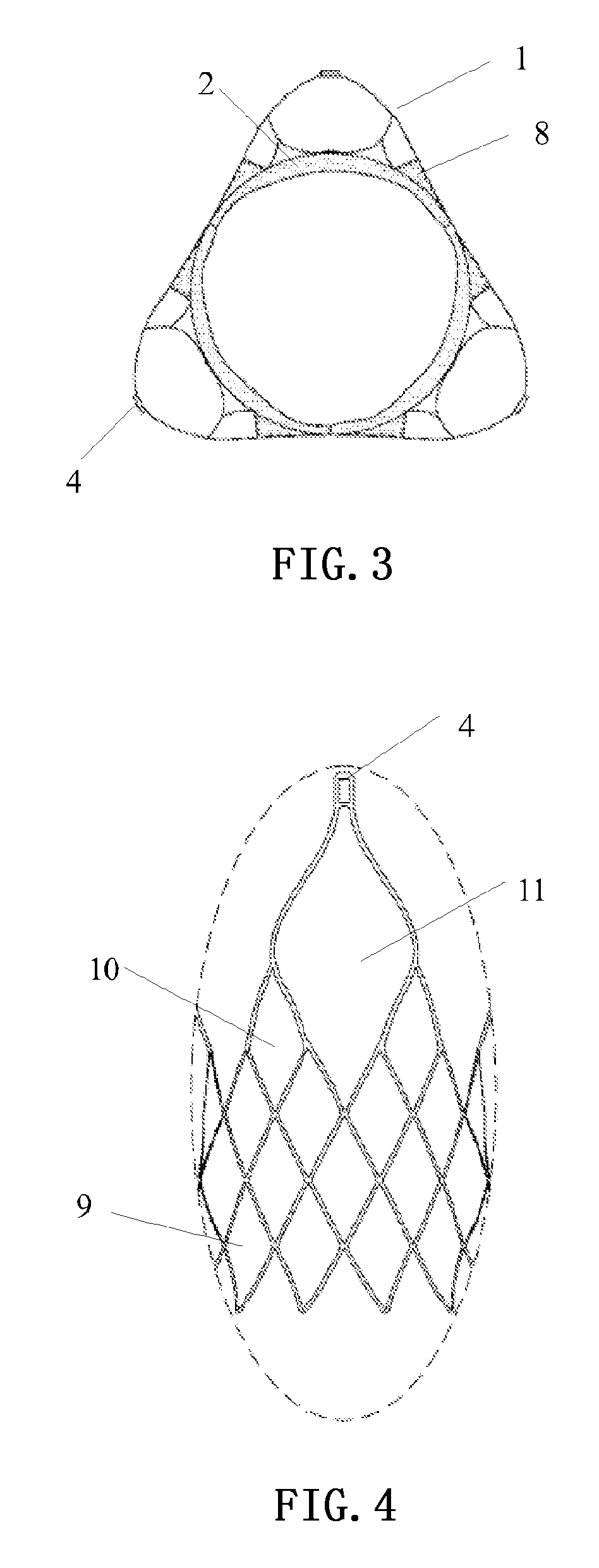
[0065]Please refer to FIGS. 1-5. FIG. 1 is a front view of the cardiac valve provided by the Embodiment 1 of the present invention, FIG. 2 is a top view of the cardiac valve provided by the Embodiment 1 of the present invention when the valve is in the closed state, FIG. 3 is a top view of the cardiac valve provided by the Embodiment 1 of the present invention when the valve is in the open state, FIG. 4 is a partially enlarged view of the stent provided by the Embodiment 1 of the present invention, and FIG. 5 is a schematic diagram of the compressed state of the cardiac valve provided by the Embodiment 1 of the present invention.

[0066]In these figures, 1 is the tubular stent, 2 is the leaflet, 3 is the skirt, 4 is the delivery and retrieval hole of the cardiac valve, 5 is the shape of the leaflet edge, 6 is the suture track of the skirt and the stent, 7 is the leaflet shut line, 8 is the suture of the leaflet and the stent, 9 is the first stent unit, 10 is the second stent unit, and...

embodiment 2

[0087]Please refer to FIGS. 13-20. FIG. 13 is a front view of the cardiac valve provided by the Embodiment 2 of the present invention, FIG. 14 is a schematic diagram of the compressed state of the cardiac valve provided by the Embodiment 2 of the present invention, FIG. 15 is a schematic diagram of the design structure of the valve provided by the Embodiment 2 of the present invention, FIG. 16 is a folded view of the valve provided by the Embodiment 2 of the present invention, FIG. 17 is an unfolded view of the suture of the valve provided by the Embodiment 2 of the present invention, FIG. 18 is a perspective view of the suture of the valve provided by the Embodiment 2 of the present invention, FIG. 19 is a schematic view of the suture track of the valve and the stent provided by the Embodiment 2 of the present invention, and FIG. 20 is a schematic view of the positional relationship between the cardiac valve provided by the Embodiment 2 of the present invention and the coronary ost...


PUM


Abstract

An invasive cardiac valve comprises a tubular stent (1) and a valve (2). One end of the tubular stent (1) is of a frusto-conical structure, the other end is wide open, and the diameter of the open end is greater than the diameter of the frusto-conical end. The valve (2) is attached to the frusto-conical end of the tubular stent (1); and a delivery and retrieval hole (4) of the cardiac valve is provided at the top of the open end of the tubular stent (1). Because the diameter of the open end is greater than the diameter of the frusto-conical end, the cardiac valve can be effectively fixed in a position of aortic annulus to prevent the cardiac valve displacement caused by the impact of the blood flow. Because the valve (2) is attached to the frusto-conical end of the tubular stent (1), the valve (2) can totally avoid the left and right coronary ostia and does not affect the haemodynamics of the coronary artery. Because a delivery and retrieval hole (4) of the cardiac valve is provided at the top of the open end of the tubular stent (1), the cardiac valve can be retrieved and reset at any time by handle control if it is found to be placed in an improper position during the release process.

Description

TECHNICAL FIELD[0001]The present invention relates to the technical field of medical apparatus and instruments and, in particular, to an invasive cardiac valve.BACKGROUND ART[0002]The heart valve is composed of extremely thin and flexible lamellar tissue, and the valve is opened and closed along with the contraction and relaxation of the heart. The heart of a normal person beats about 100,000 times per day and the valve is opened and closed 100,000 times per day. Thus, the heart valve must remain flexible and tensile, and be able to bear the pressure of the heart and the washing of the blood over a long period of time during the lifespan of a person.[0003]Cardiac valve disease is one of the most common heart diseases in China, and is mainly caused by valve damage from rheumatic fever. Coinciding with the aging population in recent years, valve degeneration (including calcification, myxoid degeneration and the like) and valve damage of metabolism disorder are increasing in China. In ...

Claims


Application Information

Patent Timeline
Patent Type & Authority Applications(United States)
IPC IPC(8): A61F2/24
CPCA61F2/2412A61F2/2415A61F2/2418A61F2002/3021A61F2230/008A61F2220/0075A61F2230/0023A61F2230/0054A61F2230/0067A61F2250/0039A61F2002/9534A61F2230/0021A61F2002/9528
Inventor YU, QIFENGLIU, XIANGWANG, YUNLEIYUE, CHENGYUNLUO, QIYI
Owner SHANGHAI MICROPORT CARDIOFLOW MEDTECH CO LTD
Why Eureka
Try Eureka